Flasher/Support Checklist
(Redirected from Flasher/Flasher Support)
Contents
- 1 Basic Settings
- 2 Chip state
- 3 Keep in mind that high frequencies (MHz) are used
- 4 Signal quality
- 5 Power Supply
- 6 Self powered target systems
- 7 VTref pin of the Flasher connected to the Vcc pin of the target system?
- 8 Universal Flashloader
- 9 If you need help, please provide us the following information:
- 10 Example oscillograms for good signal quality at different clock rates:
Basic Settings
- Please check that you have selected the correct device from the device list.
- Have you selected the correct programming mode?
- Are higher programming voltages required? Please use our "Programming voltage adapter".
https://www.segger.com/products/production/flasher/accessories/adapters/segger-programming-voltage-adapter/ - Please check the cable wiring. See XML file wiring diagram for your device.
- Have you ensured that possible rx and tx lines are properly crossed?
- Are all pins required for flashing accessible and not hard-wired to GND or VCC or other signals?
Chip state
- Is it a brand new board or has it been already programmed?
- Has the programming mode been switched or deactivated?
- Was the chip irreversibly code protected? (e.g. RDP Level 2)
- Firmwares can prevent the debug interface from being activated.
Keep in mind that high frequencies (MHz) are used
- The cables should be shorter than 30 cm.
- Try to use twisted and shielded cables.
- Try to avoid plugs and similar junctions.
- Ensure a good ground connection.
- Route the cables separately from other cables and avoid proximity to higher (AC) voltages.
Signal quality
- Is there any circuitry on the target hardware that could affect the signal quality?
- Is this circuit within the specification for programming the chip?
- The timing and data setup times must meet the requirements defined in the data sheet!
- Are external watchdog circuits connected to the reset pin? Disconnect or disable these circuits during flashing.
- Please check your signal quality using an oscilloscope. See our reference diagrams.
- Try to reduce the frequency of the target interface.
- Improve your wiring and positioning of the Flasher.
Power Supply
- The Flasher can provide up to 5V 400mA target power.
- The prerequisite is a sufficient USB power supply and an appropriate USB cable.
- If you need lower supply voltages, please use our "Target supply adapter".
https://www.segger.com/products/production/flasher/accessories/adapters/target-supply-adapter/
Self powered target systems
- How long does it take for the power supply to charge the capacitors?
- Adjust the set-up time for the "target power" to your design!
- When using an external power supply, make sure that the GND of the Flasher is properly connected to the GND of the connected device.
- Please note possible ground differences between the (PC) Flasher and the target hardware. If in doubt, please use our "USB isolator".
https://www.segger.com/products/production/flasher/accessories/isolators/usb-isolator/
VTref pin of the Flasher connected to the Vcc pin of the target system?
- If yes, please deactivate the option "Fixed VTref".
- If not, please activate "Fixed Vtref" and enter your I/O voltage in mV manually.
Universal Flashloader
- Many programming algorithms support a so-called "Verbosity Level". The higher the level is set, the more messages are displayed on the console.
- High verbosity may lead to lost messages, if you use a serial terminal. Try to use the Telnet terminal in this case.
- This gives us more information about the possible causes of your problem.
If you need help, please provide us the following information:
- Your used Flasher variant
- Your Flasher's serial number
- The exact name of your target device
- The programming mode you want to use
- The target power mode you want tot use(Self powered or powered by the Flasher)
- An excerpt from the wiring diagram for the target interface and the reset logic
- A detailed photo of the wiring from the flasher to the target.
- The settings you have chosen. Flasher.UNI or Flasher.CFG file and the J-Flash/UFL project file.
- A data file that can reproduce the behavior.
- An ASCII file containing the consoles output at the highest "verbosity level"
- Oscillograms of at least the data and clock lines
Example oscillograms for good signal quality at different clock rates:
Oscilloscope with 100MHz Bandwidth:
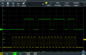
1MHz
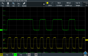
2MHz
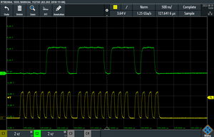
5MHz


At high clock rates you can clearly see the influence of the oscilloscope's bandwidth.
Oscilloscope with 350MHz Bandwidth:
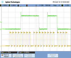
5MHz
