Kinetis Series Devices
The Kinetis device series from NXP contains different low power 32-bit microcontrollers based on ARM Cortex-M cores. The Kinetis series contains several sub-series like the Kinetis E Series, Kinetis EA (automotive) Series, Kinetis K Series, Kinetis L Series, Kinetis M Series, Kinetis V Series and Kinetis W Series.
Contents
Multiple devices in a scan-chain
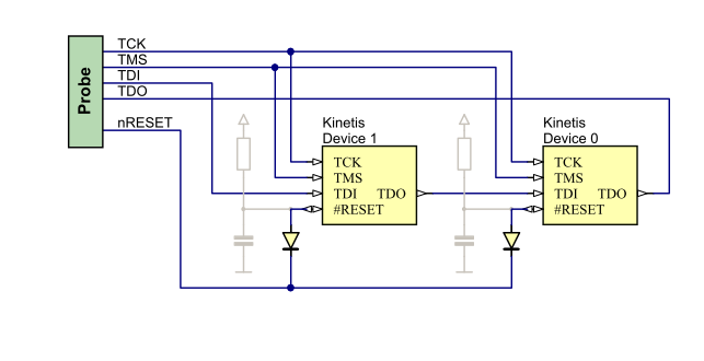
Factory-fresh Kinetis devices (empty flash), output a reset pulse every few µs because the MCU fetches an invalid instruction (0xFF). In a standard scan-chains, where the reset pin of each MCU is point-to-point wired, this causes all other devices in the JTAG chain also to be reset which of course interferes with the programming process of the device, J-Link is currently communicating with. This behavior needs to be taken into account when designing a hardware with multiple Kinetis devices in a scan-chain. The solution to this issue is to have a diode between the reset line of each MCU and the reset line of the J-Link in order to make sure that a reset for let's say Device 1 does not effect the reset line of Device 2 (see image below).
FlexNVM partitioning
Via J-Flash
There is a project in J-Flash you can use as reference.
- Open J-Flash
- Open J-Flash project. It can be found in your JLink folder: \Samples\JFlash\ProjectFiles\Freescale\MK40DX256xxx10_ConfigureDataFlash.jflash
- Open Options->Project settings->CPU. The procedure how to do a partition is described in the Init steps.
Please refer to the Freescale manual for further information on doing FlexNVM partitioning.
Via J-Link Commander
The partitioning can be realized with the Commander by using a so called J-Link command file.
Example for invocation:
JLink.exe -device MK66FX1M0xxx18 CommanderScript c:\K66FX1M0VMD18.jlink
Example content of a J-Link command file:
si 1
speed 4000
r
w1 0x40020000, 0x70
w1 0x40020007, 0x03
w1 0x40020006, 0x80
w1 0x40020005, 0x00
w1 0x40020004, 0xFC
w1 0x4002000F, 0x00
w1 0x40020000, 0x80
sleep 5
w1 0x40020007, 0x80
w1 0x4002000B, 0x32
w1 0x4002000A, 0x0D
w1 0x40020000, 0x80
sleep 5
r
For further information regarding J-Link command files, please refer to the J-Link Commander article.
Reset
It is mandatory to connect the reset pin of the Kinetis devices to J-Link. Otherwise, proper functionality and a stable connection cannot be guaranteed.
The Kinetis manuals advertise that a reset can also be issued via the MDM-AP, so no pin is required. However, this way is unreliable and does not work properly when trying to unsecure a secured device.
Secured device detected
In case of a secured Kinetis device has been detected by the J-Link DLL, the DLL will show up a dialog which allows the customer to unlock the selected device. This dialog can be suppressed by checking the "Do not show this message again" check box. The selection will be saved in the registry path below:
HKEY_CURRENT_USER -> Software -> SEGGER -> J-Link -> "DontShowAgainUnlockKinetis".
The message box can be re-enabled by changing the registry key value of "DontShowAgainUnlockKinetis" from 1 to 0.
Program Once Field
The K10 devices have a special storage within the program flash IFR called "Program Once Field". Data can be written to this field by using the "Program Once command".
It is possible to add the corresponding sequence, described in the chip user manual, into the "Init / Exit steps" in the J-Flash project settings. Theses steps are executed before (init steps) or after (exit steps) programming. For further information regarding this, please refer to chapter Settings -> Project Settings -> Flash settings in the J-Flash user guide (UM08003).
EzPort
Some Freescale Kinetis devices come with an SPI-like interface called EzPort which can be used to perform flash operation without establishing a debug interface connection. Please note that using the EzPort disables the JTAG debug interface and therefore J-Link can not establish a connection to the target device. To guarantee a proper debug connection, we recommend to assemble a pull-up resistor connected to the chip select signal of the EzPort (EZP_CS) which disables the EzPort.
