Renesas RZ/T2M
Contents
The RZ/T2M is an high-performance multi-function MPU featuring two Cortex-R52 cores.
QSPI Flash Programming Support
Before continuing with this article, please read the generic article about QSPI flash programming support: QSPI_Flash_Programming_Support
Setup
- Hardware: Renesas RZ/T2M-RSK
- Device: R9A07G075M0
- SPI NOR Flash: Macronix MX25R512 (64MB flash)
Port / Pin Configuration
| Alternate function | Port / Pin |
|---|---|
| XSPI0_DS | P14_4 |
| XSPI0_CKP | P14_6 |
| XSPI0_IO0 | P14_7 |
| XSPI0_IO1 | P15_0 |
| XSPI0_IO2 | P15_1 |
| XSPI0_IO3 | P15_2 |
| XSPI0_CS0 | P15_7 |
| XSPI0_RESET0 | P16_1 |
On specific request by Renesas, J-Link does not restore the target state after flash operations.
Parallel CFI NOR Flash Programming Support
The J-Link software supports flash programming of an externally connected parallel CFI NOR flash out-of-the-box. The pins used on the RZ/T2M-RSK are assumed by default. The external memory starts at address 0x70000000.
This may be changed in future versions so that customers have to perform the external BUS interface initilization by themselves
Reset
A device specific reset is performed containing the following steps:
- Make sure that the device halts immediately after reset (before it can execute any instruction of the user application) by setting EDECR.RCE == 1
- Reset the core and peripherals by toggling the reset pin
- Pass through the RZ/T2M Authentication process if necessary
- Power core if necessary
- Enable debug mode if necessary
- Clear the reset catch bit (EDECR.RCE == 0)
Debug Authentication
The RZ/T2M supports different authentication levels. Depending on the authentication level, debug access can be granted if the correct key is passed. How this is possible is described below.
For security products, the MDD pin must be set to the correct state.
Specifying the authentication code using J-Link Command String
This is the recommended method as the specified authentication key will be used for the whole session. This way, the key must not specified multiple times (e.g. if a reset is performed). The J-Link Command String needs to be passed to the J-Link DLL before establishing the target connection. The J-Link Command String SetCPUConnectIDCode <AuthKey> has to be used (see example below).
Example authentication key:
- AuthenticationKey0: 0x01234567
- AuthenticationKey1: 0x89ABCDEF
- AuthenticationKey2: 0x00224466
- AuthenticationKey3: 0x88AABBCC
exec SetCPUConnectIDCODE 67452301EFCDAB8966442200CCBBAA88
Specifying the authentication code using the ID Code dialog
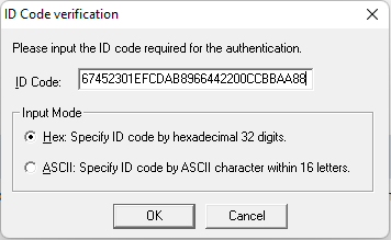
If the authentication key has not been specified using the Command String although it is required to enable debug access, the following message box will pop up which allows specifying the authentication key.
RTT
J-Link uses the AXI-AP of the device for RTT accesses.
- Supported since V7.86c of the J-Link software version, when selecting a RZ/T2M device.
- RTT control block and buffers must be placed in a memory that is accessible via AXI-AP.
- ATCM and BTCM are not suitable because they are not accessible via AXI-AP.
- AXI-AP bypasses the cache of the CPU, so RTT control block and buffers need to be in a non-cached memory area.
- RTT auto-detection: By default, J-Link scans the first 32 KB of the system RAM @ 0x1000_0000 for a RTT control block.
- Regarding cache etc., the RTT Cortex-R specifics apply.
HSS
J-Link uses the AXI-AP of the device for HSS accesses.
- Supported since V7.86c of the J-Link software version, when selecting a RZ/T2M device.
- Variables to monitor must be placed in a memory that is accessible via AXI-AP.
- ATCM and BTCM are not suitable because they are not accessible via AXI-AP.
- AXI-AP bypasses the cache of the CPU, so variables need to be in a non-cached memory area. (Otherwise only sporadic or no updates will be seen at all)
Zoned memory access
Supported since V7.86b of the J-Link software version, when selecting a RZ/T2M device.
For more information about what zoned memory accesses are: Dedicated wiki article
The following zones are available for these devices:
| Zone | Description |
|---|---|
| Default | Default memory view (memory is accessed through the core) |
| AP0 | APB-AP. Not usable for the user |
| AP1 | APB-AP view that connects to the debug registers and other CoreSight components. Not usable for the user |
| AP2 | AXI-AP. Allows DMA-like access (bypasses MMU/MPU/caches) to system memory and most peripheral registers |
Evaluation Boards
- Renesas RZ/T2M-RSK: https://wiki.segger.com/Renesas_RZ/T2M-RSK
Example Application
- Renesas RZ/T2M-RSK: https://wiki.segger.com/Renesas_RZ/T2M-RSK#Example_Project
