Setting up IP network interface
This article explains how to set up the IP interface of the different SEGGER probes that support this feature. The network interfaces can be used for remote access to the debug probe. This requires the J-Link Software and Documentation Pack, which can be downloaded here.
Contents
Setting up a WiFi interface
Currently, the J-Link WiFi is the only SEGGER probe supporting a WiFi interface. The WiFi interface can be set up in multiple ways.
Using J-Link Commander
- Connect the WiFi Probe to your computer via USB
- Start J-Link Commander (JLink.exe)
- Set up the SSID of your wireless network with the following command: SetWifi SSID <your_wifi_ssid>
- Set up the password to your wireleass network with the following command: SetWifi Pass <your_wifi_password>
- After a few seconds, the WiFi Probe should be connected to your wireless network (the green WiFi LED should be always on).
To get the IP address:
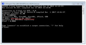
- After performing the steps listed above, issue the following command in J-Link Commander: USB
- The WiFi Probe will reconnect via USB and provide its IP address, e.g.: IP-Addr: 10.1.1.114 (DHCP)
- When connecting to the WiFi Probe later on via IP, use this IP address to establish the connection
Using J-Link Configurator
- Connect the WiFi Probe to your computer via USB
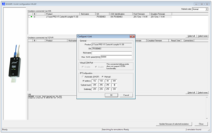
- Start J-Link Configurator (JLinkConfig.exe)
- Right-click on the WiFi Probe in the list of connected J-Links and select 'Configure'
- In the WiFi configuration section, enter the SSID and the password of your wireless network
- Click OK
- Unplug and reconnect the WiFi Probe
- Click OK
- After a few seconds, the WiFi Probe should be connected to your wireless network (the green WiFi LED should be always on).
To get the IP address:
- Start J-Link Commander (JLink.exe/JLinkExe)
- The WiFi Probe will connect via USB and provide its IP address, e.g.: IP-Addr: 10.1.1.114 (DHCP)
- When connecting to the WiFi Probe later on via IP, use this IP address to establish the connection
WiFi Probes in J-Link Configurator
WiFi Probes will usually only be shown in the Configurator if connected via USB.
For further information see: UDP broadcast
Setting up Ethernet interface
Our most advanced debug probes J-Link PRO and J-Trace PRO come with a gigabit Ethernet interface. Please note that only one connection via Ethernet is supported at once.
Setting up with a router (DHCP)
This article assumes that your debug probe is in delivery condition, which means it is configured to use DHCP. If it is not, please refer to Setting up to use DHCP. When using a router with DHCP mode enabled, setting up the Ethernet connection is rather simple.
- Connect both the host PC and the J-Link/J-Trace debug probe via Ethernet to the router.
- Now simply wait until the router assigns a IP to both devices.
- Check the IP status of the debug probe using J-Link Commander or J-Link Configurator.
- To connect to the debug probe over IP type: IP <Assigned IP address>
Setting up direct connection without DHCP to the host PC's Ethernet interface
When no router with DHCP is available, you can still configure your debug probe and host PC to connect to each other via Ethernet. To do that, additional steps are required. The following example guide will show a step-by-step configuration on a Windows system. For Linux and or Mac the principle stays the same but other steps might be required. Other ways of setting the debug probe IP address manually can be found in the J-Link user manual (UM08001_JLink).
- Connect the J-Link/J-Trace debug probe to your host PC via USB.
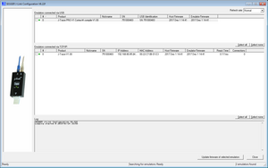
- Open the J-Link Configurator (JLinkConfig.exe) from the J-Link software installation folder.
- Set the IP address to an available address in your local network e.g. 192.168.abc.xyz where abc and xyz are free to choose from 0 up to 255 and the subnet mask to 255.255.255.0.
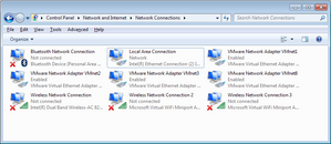
- Now go to your network adapter folder and right-click the Ethernet adapter that is to be used for this setup and open the properties.
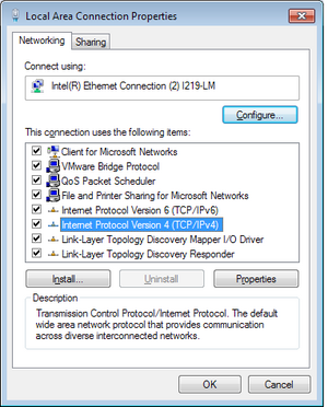
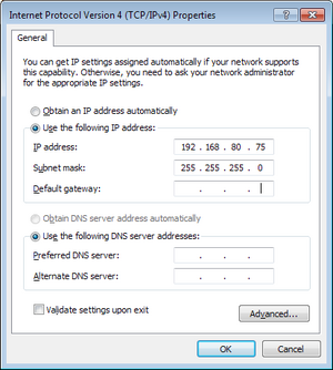
- In the properties menu, open "Internet Protocol Version 4(TCP/IPv4)" settings.
- Select "Use the following IP address:" and set the IP address to the same subnet as the J-Link/J-Trace before.
- In this example to 192.168.abc.xyz where xyz must be another value than the one chosen for the debug probe and abc must be chosen the same as before, subnet mask is again 255.255.255.0.
- After everything is set up correct, the debug probe should show up in the J-Link Configurator connected via USB and TCP/IP.
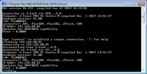
- To test the IP connection J-Link Commander from the J-Link software install folder can be used, to connect simply type: IP <Assigned IP address> and press enter.
Setting up to use DHCP
When your J-Link is configured to use a static IP address but you want to switch back to use DHCP, the J-Link needs to be re-configured. This can be done using either the J-Link Commander or the J-Link Configurator.
J-Link Configurator
- Connect the J-Link/J-Trace debug probe to your host PC via USB.
- Open the J-Link Configurator (JLinkConfig.exe) from the J-Link software installation folder.
- Set the IP Configuration to "Automatic (DHCP)"
J-Link Commander
- Connect the J-Link/J-Trace debug probe to your host PC via USB.
- Open the J-Link Commander (JLink.exe) from the J-Link software installation folder.
- Enter the command "ipaddr dhcp"
Power over Ethernet
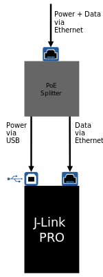
J-Link requires to be powered via its USB interface. As such, J-Link cannot be powered using PoE and only connecting a network cable.
It is possible to make use of PoE with J-Link by using a PoE splitter so that J-Link is powered via USB, but data communication happens via Ethernet.
Used IP ports and Probe discovery
The following ports are used by J-Link/J-Trace within the IP network:
| Port | Protocol | Purpose |
|---|---|---|
| 80 | TCP | Built-in web server of probe. |
| 19020 | TCP | Communication port used by PC software to communicate with probe. |
| 19020 | UDP | Discover port for auto-detection of probes in network. E.g. used by J-Link Configurator application.[1] |
| 19030 | UDP | J-Trace only. Source port on probe side to send streaming trace data via IP. Local port on PC side is dynamically assigned. PC initiates traffic. |
- ↑ See: UDP boradcast.
UDP broadcast
The Probe software uses UDP broadcasts to the Probe on port 19020 to trigger the discovery call.
As broadcasts do not leave subnets per default, only probes within the same subnet will be discovered in this case.
To allow discovery across multiple subnets, all related routers have to be configured to forward this UDP broadcast across the subnets for port UDP:19020.
For further information regarding discovery across multiple subnets, please refer to: https://stackoverflow.com/questions/379015/udp-broadcast-packets-across-subnets
The UDP discovery mechanism will usually not work for WiFi Probes.
This is because per default, most routers have UDP broadcast and UDP multicast packets disabled for WiFi networks.