ST STM32H7
This article describes device specifics of the ST STM32H7 series devices. The STM32H7 devices are Cortex-M7 based single or dual core (+ Cortex-M4) MCUs with low-power functionality.
Contents
- 1 Flash
- 2 Reset
- 3 Debug specific
- 4 Option byte programming
- 5 Securing/unsecuring the device
- 6 QSPI Support
- 7 SWO
- 8 RTT
- 9 Tracing on STM32H7 series
Flash
| Device | Range | Total size |
|---|---|---|
| Main flash memory | ||
| STM32H7xxxB | 0x0800_0000 - 0x0801_FFFF | 128 KB |
| STM32H7xxxE | 0x0800_0000 - 0x0807_FFFF | 512 KB |
| STM32H7xxxG | 0x0800_0000 - 0x080F_FFFF | 1024 KB |
| STM32H7xxxI | 0x0800_0000 - 0x081F_FFFF | 2048 KB |
| QSPI flash [1] | ||
| All | 0x9000_0000 - 0x9FFF_FFFF (max) | 256 MB (max) |
- ↑ See: QSPI Support
Reset
For the STM32H7 devices, the Cortex-M default reset strategy is used.
Debug specific
Please refer to the generic STM32 article.
Option byte programming
Please refer to the generic STM32 article.
Securing/unsecuring the device
Please refer to the generic STM32 article.
QSPI Support
The ST STM32F7 device series comes with a QUADSPI/OCTOSPI controller which allows memory mapped read accesses to any (Q)SPI flash, connected to the Quad/Octo-SPI interface of the MCU. This allows the J-Link DLL to support flash programming through the Quad/Octo-SPI interface. Unfortunately, there is no generic way how to implement flash programming because the pins used to connect the SPI flash are not defined. Different pins can be used for the same QUADSPI/OCTOSPI alternate function and therefore, for each configuration, a slightly different RAMCode (different pin initialization / flash size) is required. We have developed a flash algorithm based on the ST STM32H753-EVAL, STM32H745-Disco, STM32H7B3I-EVAL and STM32H735G-DK evaluation boards. This flash algorithms can be used to to program any common (Q)SPI flash, connected to the Quad/Octo-SPI interface of the ST STM32H753xx/50xx/45xx/43xx/A3xx/B3xx/23xx/35xx device. The flash algorithm is based on the SEGGER Flash Loader concept so it can easily be exchanged if a pin configuration, different from the one used in the example flash algorithm, is required. In such cases, please get in touch with SEGGER directly via our support system: https://www.segger.com/ticket/.
Supported pin configurations
QSPI flash programming requires special handling compared to internal flash. For more information about this, please see the QSPI Flash Programming Support article.
J-Link supports multiple pin configurations for STM32H7. The default loader is marked in bold.
| Device family | Pin configuration/loader name |
|---|---|
| STM32H72xx STM32H73xx |
CLK@PF10_nCS@PG6_D0@PD11_D1@PD12_D2@PE2_D3@PD13_D4@NA_D5@NA_D6@NA_D7@NA CLK@PB2_nCS@PG6_D0@PF8_D1@PF9_D2@PF7_D3@PF6_D4@NA_D5@NA_D6@NA_D7@NA CLK@PF10_nCS@PB6_D0@PC9_D1@PC10_D2@PE2_D3@PF6_D4@NA_D5@NA_D6@NA_D7@NA |
| STM32H74xx STM32H75xx |
CLK@PB2_nCS@PG6_D0@PF8_D1@PF9_D2@PF7_D3@PF6 CLK@PF10_nCS@PB6_D0@PF8_D1@PF9_D2@PF7_D3@PF6 |
| STM32H7Axx STM32H7Bxx |
CLK@PB2_nCS@PG6_D0@PF8_D1@PF9_D2@PF7_D3@PF6_D4@NA_D5@NA_D6@NA_D7@NA CLK@PF10_nCS@PG6_D0@PD11_D1@PD12_D2@PE2_D3@PD13_D4@NA_D5@NA_D6@NA_D7@NA CLK@PF10_nCS@PB6_D0@PC9_D1@PC10_D2@PE2_D3@PF6_D4@NA_D5@NA_D6@NA_D7@NA |
SWO
On the STM32H7 series devices from ST SWO is supported. However, a few device specifics apply which are described in the following section.
SWO register access
For most Cortex-M devices, the SWO registers are accessible by the AHB-AP. This is not the case for the STM32H7 series devices. In this case the registers need to be partially accessed by the APB-AP. If you are using software that handles SWO init without J-Link software (e.g. EWARM) then we suggest contacting the software manufacturer for more details which settings need to be applied.
- J-Link handles the current setting of this registers automatically. J-Link software version V6.33a or later is required.
- The settings are applied by a compiled .JLinkScript-file located in the J-Link software, should you need the original source, please get in touch with SEGGER directly via our support system: https://www.segger.com/ticket/.
Sample projects
Sample projects that demonstrate SWO usage are available for the following eval boards:
RTT
SEGGER's RTT can be used with a J-Link connected to a STM32H7 target device.
Sample project
For a sample Embedded Studio project, refer to the following .zip archive:
The above project was tested with the following setup:
| Target device | STM32H743ZI |
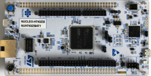
| Evalboard | NUCLEO-H743ZI2 (ST) |
| J-Link software version | V6.51b |
| Embedded Studio version | V4.18 |
Tested Hardware
Tracing on STM32H7 series
This section describes how to get started with trace on the ST STM32H7 MCUs. This section assumes that there is already a basic knowledge about trace in general (what is trace, what different implementations of trace are there, etc.). If this is not the case, we recommend to read Trace chapter in the J-Link User Manual (UM08001).
- The sample projects come with a pre-configured project file for Ozone that runs out-of-the box.
- The following sample project is designed to be used with J-Trace PRO for streaming trace, J-Link Plus for buffer tracing (TMC/ETB trace) and Ozone to demonstrate streaming trace.
- In order to rebuild the sample project, SEGGER Embedded Studio can be used.
- The examples are shipped with a compiled .JLinkScriptfile, should you need the original source, please get in touch with SEGGER directly via our support system: https://www.segger.com/ticket/.
- To create your own .JLinkScriptfile you can use the following guide as reference: How_to_configure_JLinkScript_files_to_enable_tracing
Tracing on ST STM32H743 (SEGGER STM32H7 Trace Reference Board)
Minimum requirements
In order to use trace on the ST STM32H743 MCU devices, the following minimum requirements have to be met:
- J-Link software version V6.60d or later
- Ozone V3.10b or later (if streaming trace and / or the sample project from below shall be used)
- J-Trace PRO for Cortex-M HW version V1.0 or later for streaming trace
- J-Link Plus V10 or later for TMC/ETB trace
To rebuild the project our IDE Embedded Studio can be used. The recommended version to rebuild the projects is V6.30. But the examples are all prebuild and work out-of-the box with Ozone, so rebuilding is not necessary.
Streaming trace
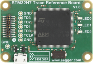
The project below has been tested with the minimum requirements mentioned above and a SEGGER STM32H7 Trace Reference Board which can be purchased on the SEGGER Website. The project sets the CPU core clock to 64 MHz and sets the trace clock to 64/2 MHz.
- Example project: ST_STM32H7_Trace_Tutorial_Project.zip
Trace buffer (TMC/ETB)
The project below is utilizing the on-chip trace buffer (it is not meant for streaming trace).
- Example Project: ST_STM32H7_TraceBuffer_Tutorial_Project.zip
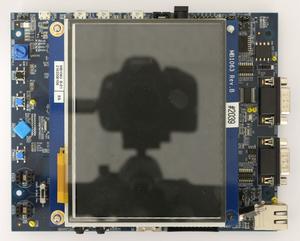
Tested Hardware
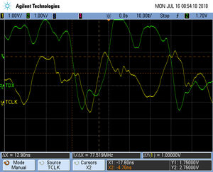
Reference trace signal quality
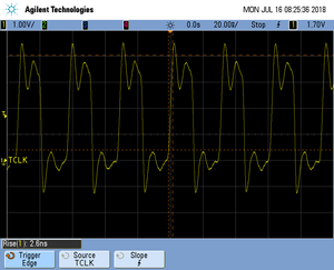
The following pictures show oscilloscope measurements of trace signals output by the "Tested Hardware" using the example project. All measurements have been performed using a Agilent InfiniiVision DSO7034B 350 MHz 2GSa/s oscilloscope and 1156A 1.5 GHz Active Probes. If your trace signals look similar on your trace hardware, chances are good that tracing will work out-of-the-box using the example project. More information about correct trace timing can be found at the following website.
Trace clock signal quality
The trace clock signal quality shows multiple trace clock cycles on the tested hardware as reference.
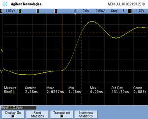
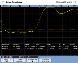
Rise time
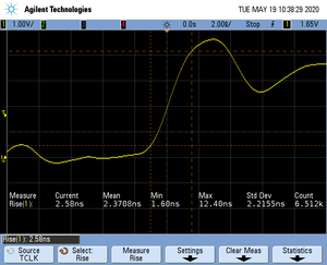
The rise time of a signal shows the time needed for a signal to rise from logical 0 to logical 1. For this the values at 10% and 90% of the expected voltage level get used as markers. The following picture shows such a measurement for the trace clock signal.
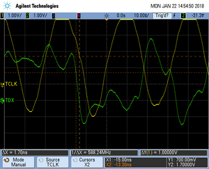
Setup time
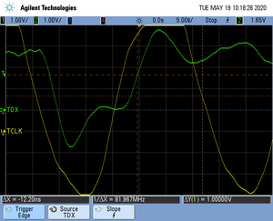
The setup time shows the relative setup time between a trace data signal and trace clock. The measurement markers are set at 50% of the expected voltage level respectively. The following picture shows such a measurement for the trace data signal 0 relative to the trace clock signal.
Tracing on ST STM32H743
Minimum requirements
In order to use trace on the ST STM32H743 MCU devices, the following minimum requirements have to be met:
- J-Link software version V6.60d or later
- Ozone V3.10b or later (if streaming trace and / or the sample project from below shall be used)
- J-Trace PRO for Cortex-M HW version V1.0 or later for streaming trace
- J-Link Plus V10 or later for TMC/ETB trace
- Tracepin connection like on the STM32H743I-EVAL board (See Specifics/Limitations for more information)
To rebuild the project our IDE Embedded Studio can be used.
Streaming trace
The project below has been tested with the minimum requirements mentioned above and a ST STM32H743I-EVAL board.
- Example Project: ST_STM32H743_400MHz_Trace.zip
- The maximum supported trace clock speed on the tested evalboard is 133 MHz due to hardware limitations (see ST manual for more information).
- The example project above sets the CPU core clock to 400 MHz and sets the trace clock to 400/6 MHz. This is due to the hardware limitations of the ST EVAL board which officially supports only up to 50 MHz. More information can be found in the ST EVAL board user manual.
- The following is a barebone example without PLL and peripheral init that should run on any related STM32H7 hardware:
ST_STM32H7_32MHz_TraceExampl_pex.zip
Trace buffer (TMC/ETB)
The projects below are utilizing the on-chip trace buffer (they are not meant for streaming trace).
- Example Project (32MHz): ST_STM32H7_32MHz_TraceBufferExampl_pex.zip
- Example Project (400MHz): ST_STM32H743_400MHz_TraceBuffer.zip
Specifics/Limitations
The STM32H7xx Productfamily has additional pins that can be used for tracing.
Usually only 5 Pins are mapped to have the trace functionality.
In this case however multiple pinout configurations are possible over different ports even.
Should you be using our trace example make sure your physical trace-pin connections are equal to the ones on the ST STM32H743I-EVAL board.
If not adjust the pin initialization accordingly.
The eval board used in the example projects has an official trace clock limit of 50 MHz due to hardware restriction on the eval board.
However the 50 MHz Traceclock should suffice for most target applications.
Should nonetheless faster trace speeds be needed multiple resistors and solder bridges need to be removed from the eval board.
More information about this can be found in the eval board user manual.
Tested Hardware
Reference trace signal quality
The following pictures show oscilloscope measurements of trace signals output by the "Tested Hardware" using the example project. All measurements have been performed using a Agilent InfiniiVision DSO7034B 350 MHz 2GSa/s oscilloscope and 1156A 1.5 GHz Active Probes. If your trace signals look similar on your trace hardware, chances are good that tracing will work out-of-the-box using the example project. More information about correct trace timing can be found at the following website.
Rise time
The rise time of a signal shows the time needed for a signal to rise from logical 0 to logical 1. For this the values at 10% and 90% of the expected voltage level get used as markers. The following picture shows such a measurement for the trace clock signal.
Setup time
The setup time shows the relative setup time between a trace data signal and trace clock. The measurement markers are set at 50% of the expected voltage level respectively. The following picture shows such a measurement for the trace data signal 0 relative to the trace clock signal.
Tracing on ST STM32H753
The STM32H753 MCU is in regards of tracing comparable to the STM32H743 so the following example projects can be used as reference: Tracing on ST STM32H743
Make sure to set the correct device in your Ozone project.
Tracing on ST STM32H7B3
The STM32H7B3 MCU is in regards of tracing comparable to the STM32H743 (Trace setup and script files).
Minimum requirements
In order to use trace on the ST STM32H7B3 MCU devices, the following minimum requirements have to be met:
- J-Link software version V6.92 or later
- Ozone V3.22a or later (if streaming trace and / or the sample project from below shall be used)
- Embedded Studio V5.32a (if the ES project shall be used)
- J-Trace PRO for Cortex-M HW version V2.0 or later for streaming trace
- J-Link Plus V10 or later for TMC/ETB trace
To rebuild the project our IDE Embedded Studio can be used. The recommended version to rebuild the projects is V6.30. But the examples are all prebuild and work out-of-the box with Ozone, so rebuilding is not necessary.
Streaming trace
- Example project: ST_STM32H7B3LI_TracePins.zip
Specifics / Limitations
The board does not have trace pins connected to the debug header by default. Please refer to the ST board manual for information about how to connect the pins.
Trace buffer (TMC/ETB)
- Example Project: ST_STM32H7B3LI_TraceBuffer.zip
Tested Hardware
Reference trace signal quality
TBD
Tracing on ST STM32H747 (dual-core)
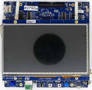
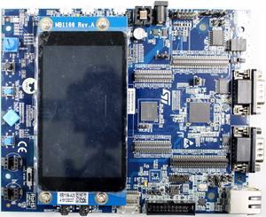
The STM32H747 is different to the MCUs listed above. It is a dual-core device with a Cortex-M7 and a Cortex-M4. The following projects have been tested with the minimum requirements mentioned and a ST STM32H747I-EVAL evaluation board.
For now, J-Trace Pro does not support tracing both cores in parallel. Therefore, a different script/project is provided here, depending on which core is supposed to be traced.
Minimum requirements
In order to use trace on the ST STM32H747 MCU devices, the following minimum requirements have to be met:
- J-Link software version V6.72b or later
- Ozone V3.10f or later (if streaming trace and / or the sample project from below shall be used)
- J-Trace PRO for Cortex-M HW version V1.0 or later for streaming trace
- J-Link Plus V10 or later for TMC/ETB trace
To rebuild the project our IDE Embedded Studio can be used. The recommended version to rebuild the projects is V6.30. But the examples are all prebuild and work out-of-the box with Ozone, so rebuilding is not necessary.
Streaming trace
STM32H747_M7
- Example project: ST_STM32H747_M7_TracePinsSample.zip
STM32H747_M4
- Example project: ST_STM32H747_M4_TracePinsSample.zip
Trace buffer (TMC/ETB)
STM32H747_M7
- Example Project: ST_STM32H747_M7_TraceBufferSample.zip
STM32H747_M4
- Example Project: ST_STM32H747_M4_TraceBufferSample.zip
Tested Hardware
Reference trace signal quality
The following pictures show oscilloscope measurements of trace signals output by the "Tested Hardware" using the example project. All measurements have been performed using a Agilent InfiniiVision DSO7034B 350 MHz 2GSa/s oscilloscope and 1156A 1.5 GHz Active Probes. If your trace signals look similar on your trace hardware, chances are good that tracing will work out-of-the-box using the example project. More information about correct trace timing can be found at the following website.
Rise time
The rise time of a signal shows the time needed for a signal to rise from logical 0 to logical 1. For this the values at 10% and 90% of the expected voltage level get used as markers. The following picture shows such a measurement for the trace clock signal.
Setup time
The setup time shows the relative setup time between a trace data signal and trace clock. The measurement markers are set at 50% of the expected voltage level respectively. The following picture shows such a measurement for the trace data signal 0 relative to the trace clock signal.
