Black Pill
This article describes specifics for using J-Link with the Black Pill board. The Black Pill board is based on a ST STM32F103. It is an Arduino nano like board and similar to the Blue Pill board. The board does not come with a standard debug connector but with 4 pins which can be used to connect the J-Link to the MCU.
Contents
Preparing for J-Link
The Blue Pill board does not come with a standard debug connector but populates the debug JTAG signals on a 4 header that can be found on the opposite of the USB interface. It has to be wired manually for the use with J-Link.
The following guide will describe how the Blue Pill can be connected to your J-Link.
Minimum requirements
- Any current J-Link model.
- J-Link software V6.61a or later
Connection setup
Connect the board with e.g. jumper wires to your J-Link probe. The following table shows how the signals should be connected on both the board and J-Link side.
| J-Link 20 pin debug interface | Pin on Black Pill board |
|---|---|
| Pin 1 (VTref) | 3V3 |
| Pin 4 (GND) | GND |
| Pin 7 (SWDIO/TMS) | SWIO |
| Pin 9 (SWCLK/TCK) | SWCLK |
| Pin 15 (nRESET) | RST/RESET (J3 - Pin 17) |
The connection setup should look similar to this example:
Note: Because of the state the board is shipped with, a connect under reset will be necessary. Therefore the RESET/RST pin has to be connected to the J-Link.
Connection verification
- Power the board via the USB port.
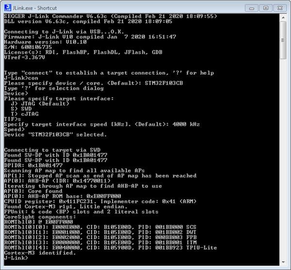
- Verify the Connection with e.g. J-Link Commander. The output should look as follows:
Example project for SEGGER Embedded Studio
The following, simple "Hello World" example project was created with the SEGGER Embedded Studio project wizard and runs out-of-the-box on the Black Pill board.
Minimum requirements
- Any current J-Link model.
- Embedded Studio Version 4.42 or later

