Difference between revisions of "CC3220 LaunchPad"
| Line 1: | Line 1: | ||
The TI CC3220 LaunPad evaluation board does come with an on board debugger (XDS110) which drives the debug signals by default. In order to be able to connect with a J-Link to the CC3220SF device, the jumpers as shown on image below needs to be removed in order to isolate the on board debugger. The J-Link needs to be connected through the 9-pin Cortex-M connector (JTAG_IN). |
The TI CC3220 LaunPad evaluation board does come with an on board debugger (XDS110) which drives the debug signals by default. In order to be able to connect with a J-Link to the CC3220SF device, the jumpers as shown on image below needs to be removed in order to isolate the on board debugger. The J-Link needs to be connected through the 9-pin Cortex-M connector (JTAG_IN). |
||
| + | If powering the board via the top USB connector, leave all four power supply jumpers connected(J21/J20/J19/J17) |
||
<div><ul> |
<div><ul> |
||
<li style="display: inline-block;"> [[File:WIKI_TI_CC3220_LaunchPad_JTAG.png|thumb|none|400px|''SOP'' (J13) configured for JTAG]] </li> |
<li style="display: inline-block;"> [[File:WIKI_TI_CC3220_LaunchPad_JTAG.png|thumb|none|400px|''SOP'' (J13) configured for JTAG]] </li> |
||
Revision as of 16:06, 24 April 2018
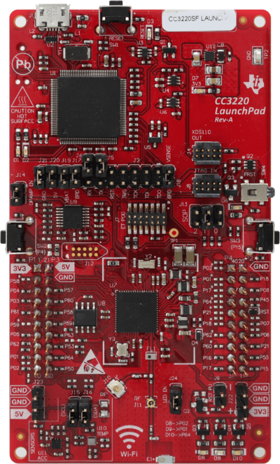
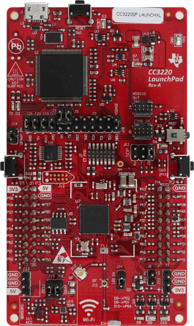
The TI CC3220 LaunPad evaluation board does come with an on board debugger (XDS110) which drives the debug signals by default. In order to be able to connect with a J-Link to the CC3220SF device, the jumpers as shown on image below needs to be removed in order to isolate the on board debugger. The J-Link needs to be connected through the 9-pin Cortex-M connector (JTAG_IN).
If powering the board via the top USB connector, leave all four power supply jumpers connected(J21/J20/J19/J17)

