Difference between revisions of "RTT Ramcode Sample for Cortex-M0+ (Keil MDK)"
| Line 19: | Line 19: | ||
Build(F7) the project and start debugging by clicking on the Debug button (Ctrl + F5) |
Build(F7) the project and start debugging by clicking on the Debug button (Ctrl + F5) |
||
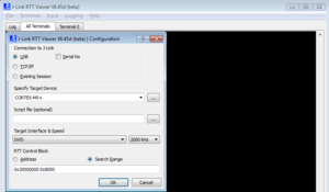
In parallel start RTT Viewer and connect with the following settings: |
In parallel start RTT Viewer and connect with the following settings: |
||
| + | [[File:CortexM0+_RTT_Settings.PNG|left|thumb|RTT Viewer Settings]] |
||
| + | |||
| + | |||
| + | |||
| + | |||
| + | |||
| + | |||
| + | |||
| + | |||
| + | |||
| + | |||
| + | |||
| + | |||
| + | |||
| + | |||
| + | |||
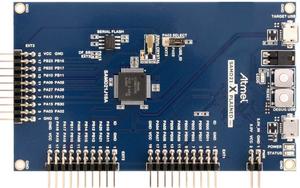
= Tested Hardware = |
= Tested Hardware = |
||
Revision as of 15:22, 8 May 2019
This article describes how to get started with RTT within RAM on a Cortex-M0+ device. This article assumes that there is already a basic knowledge about RTT in general (what is RTT, etc.). If this is not the case, we recommend to read RTT chapter in the J-Link User Manual (UM08001).
Minimum requirements
In order to use ETB trace on the ATMEL ATSAMD21 devices, the following minimum requirements have to be met:
- J-Link software version V6.44g or later
- µVision V5.24.2.0 or later (if the sample project from below shall be used)
- J-Link Plus HW version V10.1 or later
Sample project
RTT Ramcode
The following sample project is designed to be used with J-Link and Keil MDK to demonstrate RTT. The project has been tested with the minimum requirements mentioned above and a SAMD21 XPlained Pro evalboard. The sample project comes with a pre-configured project for Keil MDK that runs out-of-the box.
Manual
After donloading and unzipping the project, open it with Keil µVision V5.24.2.0 or later. Build(F7) the project and start debugging by clicking on the Debug button (Ctrl + F5) In parallel start RTT Viewer and connect with the following settings:

