Difference between revisions of "Syntacore SCR1 SDK Arty"
(→Minimum J-Link hardware requirements) |
|||
| Line 1: | Line 1: | ||
__TOC__ |
__TOC__ |
||
| − | This article describes specifics for the Syntacore |
+ | This article describes specifics for the Syntacore SCR1 Arty SDK. |
| − | + | = Minimum J-Link hardware requirements = |
|
Please note that a current J-Link model is needed for RISC-V support: [[Software and Hardware Features Overview | Overview]] |
Please note that a current J-Link model is needed for RISC-V support: [[Software and Hardware Features Overview | Overview]] |
||
| + | = Limitations = |
||
| − | == Preparing for J-Link == |
||
| + | == Maximum JTAG speed == |
||
| − | The Syntacore Arty SCR1 SDK does not come with a standard debug connector but populates the debug JTAG signals on a custom connector. Therefore, it needs to be manually wired in case J-Link shall be connected to it. |
||
| + | When debugging on the Syntacore SCR1 Arty SDK, the max. JTAG speed that can be used is 1 MHz. Speeds above 1 MHz will result in unstable operation of the debug interface on the device. '''This is not a limitation of J-Link but of the Syntacore SCR1''' |
||
| + | |||
| + | = Preparing for J-Link = |
||
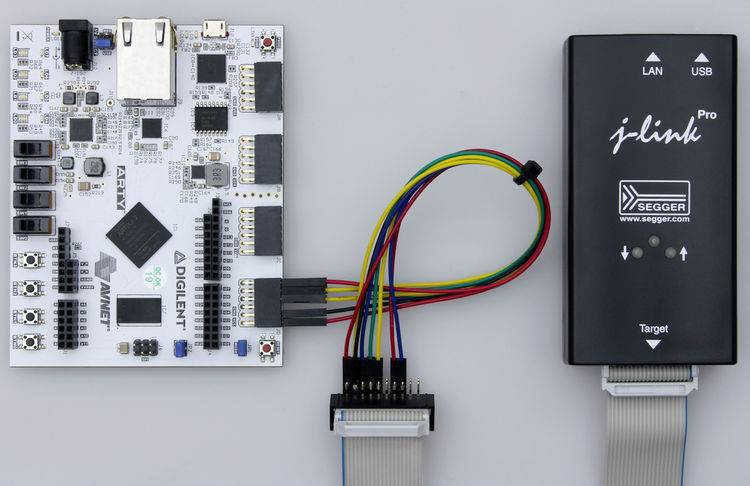
| + | The Syntacore SCR1 Arty SDK does not come with a standard debug connector but populates the debug JTAG signals on a custom connector. Therefore, it needs to be manually wired in case J-Link shall be connected to it. |
||
In the following, it is described how the pins of connector JD on the ARTY board needs to be wired to J-Link. All pins of the J-Link side refer to the standard 0.1" 20-pin connector of J-Link. |
In the following, it is described how the pins of connector JD on the ARTY board needs to be wired to J-Link. All pins of the J-Link side refer to the standard 0.1" 20-pin connector of J-Link. |
||
Revision as of 18:04, 28 February 2019
Contents
This article describes specifics for the Syntacore SCR1 Arty SDK.
Minimum J-Link hardware requirements
Please note that a current J-Link model is needed for RISC-V support: Overview
Limitations
Maximum JTAG speed
When debugging on the Syntacore SCR1 Arty SDK, the max. JTAG speed that can be used is 1 MHz. Speeds above 1 MHz will result in unstable operation of the debug interface on the device. This is not a limitation of J-Link but of the Syntacore SCR1
Preparing for J-Link
The Syntacore SCR1 Arty SDK does not come with a standard debug connector but populates the debug JTAG signals on a custom connector. Therefore, it needs to be manually wired in case J-Link shall be connected to it.
In the following, it is described how the pins of connector JD on the ARTY board needs to be wired to J-Link. All pins of the J-Link side refer to the standard 0.1" 20-pin connector of J-Link.
| Pin JD (ARTY) | Pin J-Link | Description |
|---|---|---|
| 3 | 3 | nTRST |
| 4 | 9 | TCK |
| 7 | 13 | TDO |
| 8 | 5 | TDI |
| 9 | 15 | nRESET |
| 10 | 7 | TMS |
| 11 | 4 | GND |
| 12 | 1 | VCC/VTref |
Note: The pins on the JD connector are numbered as follows:
| 6 | 5 | 4 | 3 | 2 | 1 |
| 12 | 11 | 10 | 9 | 8 | 7 |
