Tracing on ST STM32H743
Contents
This article describes how to get started with trace on the ST STM32H743 MCU. This article assumes that there is already a basic knowledge about trace in general (what is trace, what different implementations of trace are there, etc.). If this is not the case, we recommend to read Trace chapter in the J-Link User Manual (UM08001). The ST STM32H743 MCU implements tracing via pins , so a J-Trace can be used for tracing.
Minimum requirements
In order to use trace on the ST STM32H743 MCU devices, the following minimum requirements have to be met:
- J-Link software version V6.22f or later
- Ozone V2.54b or later (if streaming trace and / or the sample project from below shall be used)
- J-Trace PRO for Cortex-M HW version V1.0 or later
- Tracepin connection like on the STM32H743I-EVAL board (See Specifics/Limitations for more information)
Sample project
Streaming trace
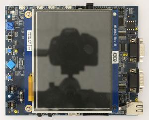
The following sample project is designed to be used with J-Trace PRO and Ozone to demonstrate streaming trace. The project has been tested with the minimum requirements mentioned above and a ST STM32H743I-EVAL board. The sample project comes with a pre-configured project file for Ozone that runs out-of-the box. In order to rebuild the sample project, SEGGER Embedded Studio can be used.
The maximum supported trace clock speed on the tested evalboard is 133 MHz due to hardware limitations (see ST manual for more information).
The following is a barebone example without PLL and peripheral init that should run on any related STM32H7 hardware: ST_STM32H7_32MHz_TraceExampel.zip
Note: The example is shipped with a compiled .JLinkScriptfile, should you need the original source it can be requested at support@segger.com
The following example project sets the CPU core clock to 400 MHz and sets the trace clock to 400/6 MHz. This is due to the hardware limitations of the ST EVAL board which officially supports only up to 50 MHz. More information can be found in the ST EVAL board user manual.
Specifics/Limitations
The STM32F7xx Productfamily has additional pins that can be used for tracing. Usually only 5 Pins are mapped to have the trace functionality. In this case however multiple pinout configurations are possible over different ports even. Should you be using our trace example make sure your physical tracepin connections are equal to the ones on the ST STM32H743I-EVAL board. If not adjust the pin initialization accordingly.
The eval board used in the example projects has an official trace clock limit of 50 MHz due to hardware restriction on the eval board. However the 50 MHz Traceclock should suffice for most target applications. Should nonetheless faster trace speeds be needed multiple resistors and solder bridges need to be removed from the eval board. More information about this can be found in the eval board user manual.
