nRF52 Series Devices
Contents
Flash programming
Access control list
The nRF52 series incorporate a so called access control list (ACL) peripheral which can be configured at runtime to inhibit reading from certain flash ranges (not to be confused with the device's readout protection feature) as well as reprogramming them. As the ACL registers are write-once after reset, it is highly recommended that the ACL is not used during debug as this limits the debugging capabilities. The following operations will no longer work in case the ACL is used:
- Single stepping code in read-protected regions
- Unlimited flash breakpoints
- Reprogramming the device without prior resetting it (e.g. modifying flash contents during a debug session via the memory window)
Note: There is no backdoor or similar implemented on this device to bypass the ACL for debugging purposes.
Flash breakpoints
SWO
On the nRF52 series devices from Nordic Semiconductor, SWO is supported. However, a few device specifics apply which are described in the following section.
Clock source
For most devices, the SWO clock is derived from the current MCU clock. This is also the case for the nRF52 series devices. However on these devices, the SWO clock has an additional fixed divider. So when the MCU Clock is set to maximum 64 MHz the SWO clock is only maximum half of that which is 32 MHz. Depending of the setting in the TRACECONFIG register, this value can get divided down even further.
Note: J-Link handles the current setting of this register automatically when calculating the SWO speed to be used. J-Link software version V6.30i or later is required.
Note: When selecting the CPU frequency in third party IDEs for J-Link SWO usage, select 64 MHz for the nRF52 series devices. When using Embedded Studio set the "Trace Clock Speed" to 32 MHz and "SWO Baud Rate" to 16 MHz. Keep in mind that your J-Link probe must support such speeds. An example project for Embedded Studio can be found in the following section.
Sample projects
Sample projects that demonstrate SWO usage are available for the following eval board: PCA10040
SWO Viewer Sample
This project was created with Embedded Studio V3.40. The SWO print stream can be made visible by either using JLinkSWOViewer or Ozone with the project enclosed in the Embedded Studio project.
ES tracing sample
This project was created with Embedded Studio V4.18. The Trace settings assume that a J-Link Base or higher is used. If you are using a J-Link OB make sure to reduce the SWO Baud Rate in the project settings to a supported value e.g. 4 MHz.
Note: For the nRF52 series target specific SWO pin init is needed. This is handled in this sample in the nRF_Target.js file under ./nRF/Scripts Simply use this file in your own Embedded Studio SWO application to make sure all target specific init steps are executed.
Softdevice
Nordic Semiconductor offers a so called softdevice which acts like a boot loader for Bluetooth related communication on ther nRF device series. If a application is programmed that is using softdevice API you will need to download the softdevice first before downloading your application.
Sample project
The latest Nordic nRF5 SDK contains numerous example projects which work out-of-the-box with Embedded Studio. In these the softdevice loading is handled automatically. To be able to use Ozone now the PC and SP must be set correctly on the bootloader/softdevice that is programmed: Start debug session with bootloader
An example Ozone project for SDK application "ble_app_blinky" for the PCA10040 eval board can be found here: Ozone project
Monitor Mode Debugging on Nordic nRF52
This section will show a how to set up monitor mode debugging with a nRF52 target device with SEGGER Embedded Studio and Ozone. For general information about the monitor mode see here. An example setup for the nRF52840-DK that runs out of the box in Ozone and Embedded Studio can be found here: nRF52_SDK16_Monitor_Mode.zip
Embedded Studio
Prerequisites
- Embedded Studio 4.52b or later
- nRF52 SDK16 or later
- Example project ble_peripheral/ble_app_blinky/pca10056/s140/ses from nRF52 SDK
How to
- Open the emProject file with Embedded Studio
- Add monitor sources to your project: https://www.segger.com/products/debug-probes/j-link/technology/monitor-mode-debugging/
- (optional) Add SEGGER Hardfaulthandler files to your project, you can get them either here, or from the example project above
- Set include path in Preprocessor project options so JLINK_MONITOR.h gets included
- Edit main and set priority of DebugMonitor_IRQn to lowest priority
- Set Jlinkscript file in Embedded Studio project that enables monitor mode and sets offset to application vector table: https://wiki.segger.com/Generic_IDE#Enable_Monitor_Mode_Debugging
- Make sure the app_timer is disabled on monitor mode entry and enabled on exit if you are using an example from the Nordic SDK
- Make sure the Watchdog is fed if active
If all this points are considered you should be able to halt code execution and use breakpoints with the nRF52 target device and softdevice.
Ozone
Ozone can also be used to debug with monitor mode enabled. First make sure your target application is set up as explained in Embedded Studio section above. The example project above has been tested with Ozone V3.10h.
How to
- Create new Ozone project with the project wizard for your nRF52 target device
- Edit the Ozone project so the softdevice is downloaded correctly and PC and SP are set at the beginning of the softdevice so the application boots correctly
- Set Monitor Mode JLinkScript in Ozone: https://wiki.segger.com/Generic_IDE#Enable_Monitor_Mode_Debugging
Tracing on nRF52832
An example project for this device can be found here: Tracing on Nordic Semiconductor nRF52832
Tracing on nRF52833
This article describes how to get started with trace on the Nordic nRF52833 MCU. This article assumes that there is already a basic knowledge about trace in general (what is trace, what different implementations of trace are there, etc.). If this is not the case, we recommend to read Trace chapter in the J-Link User Manual (UM08001). The Nordic nRF52833 MCU implements tracing via pins, so a J-Trace can be used for tracing.
Minimum requirements
In order to use trace on the Nordic nRF52833 MCU devices, the following minimum requirements have to be met:
- J-Link software version V6.56a or later
- Ozone V2.70a or later (if streaming trace and / or the sample project from below shall be used)
- J-Trace PRO for Cortex-M HW version V1.0 or later
The recommended version to rebuild the projects is ES V6.30. But the examples are all pre-build and work out-of-the box with Ozone, so rebuilding is not necessary.
Sample project
Streaming trace
The following sample project (for Nordic nRF52833-DK) is designed to be used with J-Trace PRO and Ozone to demonstrate streaming trace. The project has been tested with the minimum requirements mentioned above and a nRF52833-DK board. The sample project comes with a pre-configured project file for Ozone that runs out-of-the box. In order to rebuild the sample project, SEGGER Embedded Studio can be used.
Nordic_nRF52833_Trace_Example.zip
Note: The example is shipped with a compiled .JLinkScriptfile, should you need the original source, please get in touch with SEGGER directly via our support system: https://www.segger.com/ticket/.
To create your own .JLinkScriptfile you can use the following guide as reference: How_to_configure_JLinkScript_files_to_enable_tracing
Specifics/Limitations
The Nordic Semiconductor nRF52832 MCU uses a traceclock that is independent from the CPU clock. By hardware it is limited to maximum 16 MHz TCLK.
- As for many other MCUs from Nordic, the trace clock for this MCU is not linked to the CPU clock.
- The Nordic nRF52833-DK comes without a trace pin header. It has to be soldered onto the board by the user.
- To make trace work correctly on this evaluation board, the SW7 switch needs to be set to "Alt.".
Tested Hardware
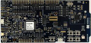
This sample project was tested on a Nordic nRF52833-DK evaluation board.
Reference trace signal quality
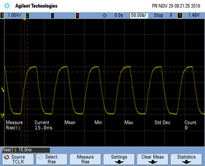
The following pictures show oscilloscope measurements of trace signals output by the "Tested Hardware" using the example project. All measurements have been performed using a Agilent InfiniiVision DSO7034B 350 MHz 2GSa/s oscilloscope and 1156A 1.5 GHz Active Probes. If your trace signals look similar on your trace hardware, chances are good that tracing will work out-of-the-box using the example project. More information about correct trace timing can be found at the following website.
Trace clock signal quality
The trace clock signal quality shows multiple trace clock cycles on the tested hardware as reference.
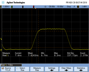
Rise time
The rise time of a signal shows the time needed for a signal to rise from logical 0 to logical 1. For this the values at 10% and 90% of the expected voltage level get used as markers. The following picture shows such a measurement for the trace clock signal.
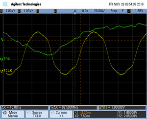
Setup time
The setup time shows the relative setup time between a trace data signal and trace clock. The measurement markers are set at 50% of the expected voltage level respectively. The following picture shows such a measurement for the trace data signal 0 relative to the trace clock signal.
Tracing on nRF52840
An example project for this device can be found here: Tracing on Nordic Semiconductor nRF52840


