Flasher SECURE/How to configure a TELP for STM32Gxxx with user-defined SECxR values
The STM32G range of ST's Cortex-M microcontrollers has a number of security features to protect intellectual property (IP). As some of these features may conflict with each other as well as with specific measures required for secure programming with a TELP, some care must be taken when setting these security features to achieve the expected result.
Preface
A TELP works in 2 main steps. In the first step, the secure bootloader (SBL) is programmed. In the second step, the SBL communicates with the Flasher Secure via an encrypted communication channel to obtain the actual customer data to be programmed into the flash. Please note that as soon as data has been provided for the memory area in which the SBL is located, subsequent programming via TELP is no longer possible, as the SBL automatically deletes itself from the system. Due to the characteristics of the STM32Gxx line, various security features can only be activated at certain times.
A brief excursus on the most important security features and their impact on TELP.
Read protection (RDP)
Read protection should prevent the read back of flash content of the MCU. There are 3 levels of protection.
The read protection is activated by setting the RDP option byte and then, by applying a system reset to reload the new RDP option byte. The read protection protects the flash main memory, the option bytes, the backup registers (TAMP_BKPxR in the RTC) and the CCM SRAM.
| RDP byte value | RDP complement value | Read protection level |
|---|---|---|
| 0xAA | 0x55 | Level 0 (production value) |
| Any value except 0xAA or 0xCC | Any value (not necessarily complementary) except 0x55 and 0x33 | Level 1 |
| 0xCC | 0x33 | Level 2 |
Level 0: no protection
Read, program and erase operations into the flash main memory area are possible. The option bytes, the CCM SRAM and the backup registers are also accessible by all operations.
Level 1: Read protection
This is the default protection level when RDP option byte is erased. It is defined as well when RDP value is at any value different from 0xAA and 0xCC, or even if the complement is not correct.
- User mode: Code executing in user mode (Boot Flash) can access flash main memory, option bytes, CCM SRAM and backup registers with all operations.
- Debug, boot RAM and bootloader modes: In debug mode or when code is running from boot RAM or bootloader, the flash main memory, the backup registers (TAMP_BKPxR in the RTC) and the CCM SRAM are totally inaccessible. In these modes, a read or write access to the flash generates a bus error and a Hard Fault interrupt.
Level 2: No debug
In this level, the protection level 1 is guaranteed. In addition, the Cortex ®-M4 debug port, the boot from RAM (boot RAM mode) and the boot from System memory (bootloader mode) are no more available. In user execution mode (boot FLASH mode), all operations are allowed on the flash main memory. On the contrary, only read operations can be performed on the option bytes.
A change from RDP level 0 to any other level is easily possible. A change from level 1 back to level 0 will trigger a mass erase. There is no way back from level 2 to any lower level.
Proprietary code readout protection (PCROP)
A part of the flash memory can be protected against read and write from third parties. The protected area is execute-only: it can only be reached by the STM32 CPU, as an instruction code, while all other accesses (DMA, debug and CPU data read, write and erase) are strictly prohibited. Depending of the DBANK mode, it allows either to specify one PCROP zone per bank in dual bank mode or to specify two PCROP zones for all memory.
Any read access performed through the D-bus to a PCROP protected area triggers the RDERR flag error.
Any PCROP protected address is also write protected and any write access to one of these addresses triggers WRPERR.
Any PCROP area is also erase protected. Consequently, any erase to a page in this zone is impossible (including the page containing the start address and the end address of this zone). Moreover, a software mass erase cannot be performed if one zone is PCROP protected.
Write protection (WRP)
The user area in flash memory can be protected against unwanted write operations. When WRP is active, it cannot be erased or programmed. Consequently, a software mass erase cannot be performed if one area is write-protected.
Securable memory area
This is an area of code that can be executed only once at boot, and never again unless a new reset occurs. The main purpose of the securable memory area is to protect a specific part of flash memory against undesired access. This is a mean to isolate first stage firmware boot together with its sensitive assets (keys) from the rest of the application code. This allows implementing root of trust solution such as secure boot. Securable memory area is located in the main flash memory. It is dedicated to executing trusted code. When not secured, the securable memory behaves like the remainder of main flash memory. When secured (the SEC_PROT1 (or SEC_PROT2) bit of the FLASH_CR register set), any attempt to program or erase in a secure memory area generates a write protection error (WRPERR flag is set) and any attempt to read from it generates a read error (RDERR flag is set)
It can be modified only in RDP Level 0. Its content is erased upon changing from RDP Level 1 to Level 0, even if it overlaps with PCROP pages.
Constraints of setting security features in TELP
As is easy to see, most features will prevent successful programming and verification if they are activated anywhere other than at the very end of step 2 of secure programming. So as a rule of thumb, you need to provide the data for security features in the custom data file with the data for the option bytes. There are two exceptions for this rule:
- RDP level, and
- Securable memory areas.
In the first case, the SBL already sets the RDP level to level 1 by programming the RDP pattern of 0xBB. The RDP pattern must not be set to a value of 0xAA later using user-defined data, as this would trigger an immediate mass erase. If it is desired to set RDP level 2, this can only be done with the user-defined data.
For the Securable memory areas, these must be set in the Exit steps of step #1 of the TELP programming, otherwise the RDP level 1 set by SBL will prevent a successful setting.
Setting the Securable memory areas for TELP
For simple setting of the values for SECxR option bytes, SEGGER recommends using the template mechanism in the U-Flash. This section explains how to set up a template with custom provided SECxR settings.
Templates are a convenient way to create partially configured U-Flash projects for target devices that can be used as a basis for projects with customized presets.
Creating a template
To create a template, simply configure a project as you normally would. However, it is not necessary to specify every detail for a template, e.g. it is perfectly fine that no data file is specified.
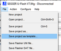
Do not try to download this project to Flasher. To save this project as a template do not use the "Save" button but use in menu "File" > "Save Project as template ..."
The templates are stored in a SEGGER Flasher sub-folder in the user home directory. For Windows for instance in the folder %LOCALAPPDATA%/SEGGER/Flasher/Templates/.
Using a template
If not already provided by SEGGER with the TELP, create a template as described above. A template serves as an "already partially configured" device. It is therefore available in the device selection dialog.
- Open the device selection dialog from the main window of U-Flash by either:
- Step #1: button "Select device", or
- "Configure > Select device …"
- Select the tab "Templates".
- Select the template suitable for your needs from the list.
- Carry out configuration, save and download to the flasher as with a normal U-Flash project. The only difference is that some settings may already be preset differently from the standard device.
Configuring the Securable memory areas
- Start as described in Using a template.
- Open the device configuration (Step #4: button "Configure project" or "Configure" > "Project Settings …" or
Alt + F7.
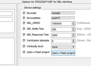
- In the right part of configuration window click the button "Open J-Flash project".
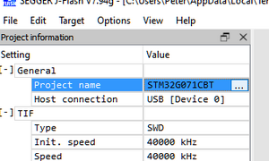
- In the J-Flash project window that opens, click on button "…" next to "Project name" or "Options" > "Project Settings" or
Alt + F7to open the project settings.
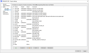
- In the left select "MCU" > "Exit steps" to open the editor.
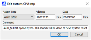
- Locate the steps annotated with
"Write FLASH_SEC1R option bytes. OBL launch will be done at next system reset" or similar.- Edit the data (button "Edit" or just double-click) according the needs.
- Close the step editor with "OK"
- close the project settings with "OK"
- Save the J-Flash project to update the J-Flash in the template ("File" > "Save" or
Ctrl + S - Close the U-Flash project settings with "OK"
- Save as template
- to new name to provide an additional template, or
- with same name to update the current template to the new settings.
To configure a target, use the altered template as starting point.
