Difference between revisions of "ST SR6PX-EVBC4000P"
(→Preparing for J-Link) |
|||
| Line 8: | Line 8: | ||
*Power the board via J1 (12V). |
*Power the board via J1 (12V). |
||
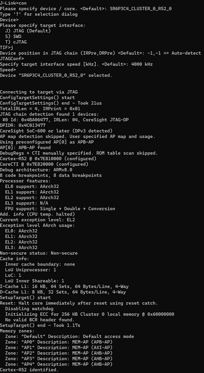
* Verify the Connection with e.g. [https://wiki.segger.com/J-Link_cannot_connect_to_the_CPU#Verify_functionality_using_J-Link_Commander J-Link Commander]. The output should look as follows: |
* Verify the Connection with e.g. [https://wiki.segger.com/J-Link_cannot_connect_to_the_CPU#Verify_functionality_using_J-Link_Commander J-Link Commander]. The output should look as follows: |
||
| − | [[File: |
+ | [[File:ST_SR6PX-EVBC4000P_SR6P3C4_connect.png|400px]] |
Revision as of 19:50, 11 December 2023
Contents
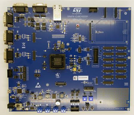
This article describes specifics for the ST SR6PX-EVBC4000P evaluation board.

Preparing for J-Link
- Connect the J-Link to P1.
- Power the board via J1 (12V).
- Verify the Connection with e.g. J-Link Commander. The output should look as follows:
