Configure required pins for trace output
1. Create a file for the device
/*-------------------------------------------------------------------
** Define the function to enable the trace port
**-----------------------------------------------------------------*/
FUNC void EnableTPIU(void) {
  _WDWORD(0x40086790, 0x00000032); // Configure PF_4 AS FUNC2
  _WDWORD(0x40086794, 0x00000033); // Configure PF_5 as FUNC3
  _WDWORD(0x40086798, 0x00000033); // Configure PF_6 as FUNC3
  _WDWORD(0x4008679C, 0x00000033); // Configure PF_7 as FUNC3
  _WDWORD(0x400867A0, 0x00000033); // Configure PF_8 as FUNC3
}

/*-------------------------------------------------------------------
** Invoke the function at debugger startup
**-----------------------------------------------------------------*/
EnableTPIU();
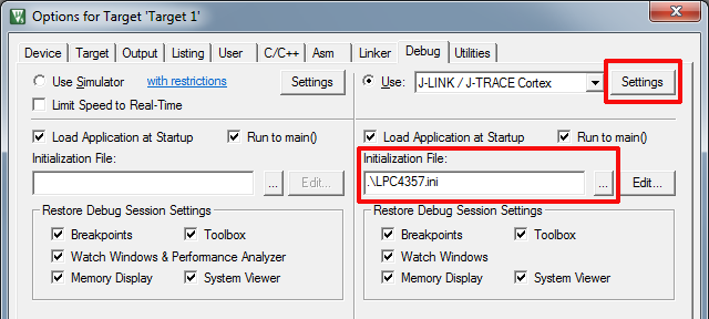
2. Set the file as initialization file
- Open the dialog "Options for Target - Debug".

- Set the created file as Initialization File.
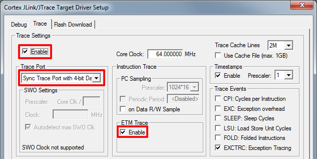
Configure µVision for ETM trace
- Click Settings to open the "Target Driver Setup" dialog.
- Click the Trace tab.

- Set Enable and ETM Trace Enable.
- Set Trace Port to "Sync Trace Port with 4-bit Data".
- The Core Clock must be adjusted accordingly the device configuration.
- Start the debugging session and open an "Instruction Trace" window.

