Arduino Nano 33 BLE
This article describes how a J-Link probe can be used together with an Arduino Nano 33 BLE board.
Contents
Minimum requirements
- Any J-Link
- J-Link software V6.86a or later
- Embedded Studio Version 5.10b or later
- Wires and solder equipment to create connector
Preparing for J-Link
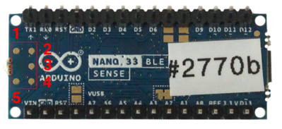
The Arduino Nano 33 BLE board does not come with an external debug interface connector, but the required connections are exposed on the back side on test points as follows:
To these test points flying wires can be soldered which then can be connected to the J-Link input pins. For this example we used the .1" 20-pin ribbon cable that is shipped with each J-Link that offers that 20 pin input type and cut it in half. Now the necessary cables just need to be stripped and can be soldered to the test points. The following table describes the pinning and how it should be connected to the J-Link 20-pin input.
| Arduino Board | J-Link 20-pin input |
|---|---|
| 1 | nRESET (pin 15) |
| 2 | GND (pin 4) |
| 3 | SWCLK (pin 9) |
| 4 | VTREF (pin 1) |
| 5 | SWDIO (pin 7) |
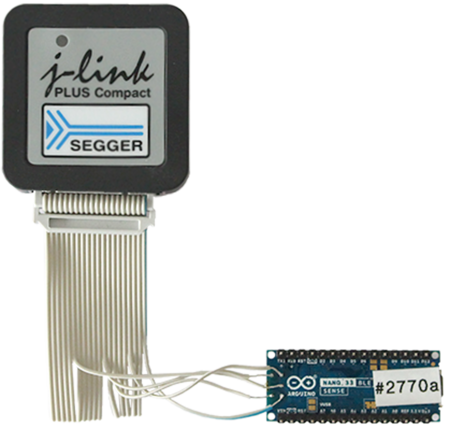
In this example we are using a J-Link Plus Compact. The resulting connection will then look like this:
- Power the board via the USB-Mini port
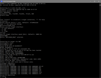
- Verify the Connection with e.g. J-Link Commander. The output should look as follows:
Debugging in SEGGER Embedded Studio
Example projects for SEGGER Embedded Studio
The following example project was created with the SEGGER Embedded Studio project wizard and runs out-of-the-box on the Arduino Nano 33 BLE board. It is a simple Hello World sample and can be downloaded here:


