Difference between revisions of "CC3220 LaunchPad"
| Line 1: | Line 1: | ||
| + | __TOC__ |
||
| + | = How to connect with J-Link = |
||
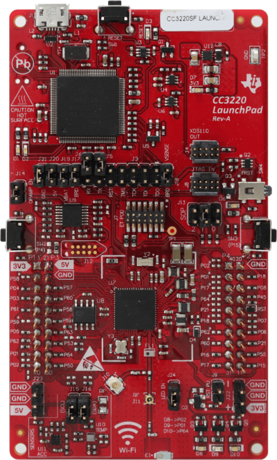
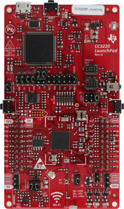
The TI CC3220 LaunchPad evaluation board does come with an on board debugger (XDS110) which drives the debug signals by default. In order to be able to connect with a J-Link to the CC3220SF device, the jumpers as shown on image below needs to be removed in order to isolate the on board debugger. The J-Link needs to be connected through the 9-pin Cortex-M connector (JTAG_IN). |
The TI CC3220 LaunchPad evaluation board does come with an on board debugger (XDS110) which drives the debug signals by default. In order to be able to connect with a J-Link to the CC3220SF device, the jumpers as shown on image below needs to be removed in order to isolate the on board debugger. The J-Link needs to be connected through the 9-pin Cortex-M connector (JTAG_IN). |
||
If powering the board via the top USB connector, leave all four power supply jumpers connected(J21/J20/J19/J17) |
If powering the board via the top USB connector, leave all four power supply jumpers connected(J21/J20/J19/J17) |
||
| − | If powering the board via an external power supply, remove all four power supply jumpers (J21/J20/J19/J17) |
+ | If powering the board via an external power supply, remove all four power supply jumpers (J21/J20/J19/J17) |
| + | |||
| + | To use the Bord in SWD, ''SOP'' (J13) needs to be set to ''0'' and to use it in JTAG mode, ''SOP'' (J13) needs to be set to ''1'': |
||
<div><ul> |
<div><ul> |
||
<li style="display: inline-block;"> [[File:WIKI_TI_CC3220_LaunchPad_JTAG.png|thumb|none|400px|''SOP'' (J13) configured for JTAG]] </li> |
<li style="display: inline-block;"> [[File:WIKI_TI_CC3220_LaunchPad_JTAG.png|thumb|none|400px|''SOP'' (J13) configured for JTAG]] </li> |
||
<li style="display: inline-block;"> [[File:WIKI_TI_CC3220_LaunchPad_SWD.png|thumb|none|400px|''SOP'' (J13) configured for SWD]] </li> |
<li style="display: inline-block;"> [[File:WIKI_TI_CC3220_LaunchPad_SWD.png|thumb|none|400px|''SOP'' (J13) configured for SWD]] </li> |
||
</ul></div> |
</ul></div> |
||
| + | |||
| + | = Using TI CC3220 LaunchPad with JTAG-/SWD-Isolators = |
||
| + | Unfortunately, the board is not able to supply the JTAG- or SWD-Isolator with the necessary power (40 mA peak, 25 mA typ. consumption). |
||
| + | Therefore it is required to supply the target side with an additional external 3.3V power source. |
||
Revision as of 15:45, 17 December 2019
How to connect with J-Link
The TI CC3220 LaunchPad evaluation board does come with an on board debugger (XDS110) which drives the debug signals by default. In order to be able to connect with a J-Link to the CC3220SF device, the jumpers as shown on image below needs to be removed in order to isolate the on board debugger. The J-Link needs to be connected through the 9-pin Cortex-M connector (JTAG_IN).
If powering the board via the top USB connector, leave all four power supply jumpers connected(J21/J20/J19/J17)
If powering the board via an external power supply, remove all four power supply jumpers (J21/J20/J19/J17)
To use the Bord in SWD, SOP (J13) needs to be set to 0 and to use it in JTAG mode, SOP (J13) needs to be set to 1:
Using TI CC3220 LaunchPad with JTAG-/SWD-Isolators
Unfortunately, the board is not able to supply the JTAG- or SWD-Isolator with the necessary power (40 mA peak, 25 mA typ. consumption). Therefore it is required to supply the target side with an additional external 3.3V power source.

