Difference between revisions of "Flasher Hub - UART Port"
(→Connection) |
|||
| (5 intermediate revisions by the same user not shown) | |||
| Line 2: | Line 2: | ||
<!-- Image source: [[Media:FH_UART_Port.odg]] --> |
<!-- Image source: [[Media:FH_UART_Port.odg]] --> |
||
| − | UART Port, formerly known as "UART Transceiver", is a feature of Flasher Hub |
+ | UART Port, formerly known as "UART Transceiver", is a feature of Flasher Hub that makes it possible to communicate with a target UART. |
__TOC__ |
__TOC__ |
||
| Line 16: | Line 16: | ||
# Make sure the UART Port feature is active |
# Make sure the UART Port feature is active |
||
# Configure and enable the UART Port for the desired module position |
# Configure and enable the UART Port for the desired module position |
||
| − | #* This can be done via the terminal (see #TERMINAL command) or the web interface |
+ | #* This can be done via the terminal (see [[Flasher_Hub_-_Remote_control#Command_.23TERMINAL | #TERMINAL command]]) or the web interface (see [[Flasher_Hub_-_Web_server#UART_page | UART page]]) |
# Open a TCP/IP connection to the UART Port |
# Open a TCP/IP connection to the UART Port |
||
# Data sent to the UART Port via TCP/IP is forwarded to the target UART |
# Data sent to the UART Port via TCP/IP is forwarded to the target UART |
||
| Line 37: | Line 37: | ||
| 2 || 2002 |
| 2 || 2002 |
||
|- |
|- |
||
| − | | 3 || |
+ | | 3 || 2003 |
|- |
|- |
||
| [...] || [...] |
| [...] || [...] |
||
| Line 47: | Line 47: | ||
Once the UART Port feature is active, UART Ports for selected modules can be enabled using |
Once the UART Port feature is active, UART Ports for selected modules can be enabled using |
||
| − | * the |
+ | * the [[Flasher_Hub_-_Web_server#UART_page | UART page of the web interface]] or |
| − | * the |
+ | * the [[Flasher_Hub_-_Remote_control#Command_.23TERMINAL | #TERMINAL command]] |
== UART Settings == |
== UART Settings == |
||
| Line 57: | Line 57: | ||
* Parity |
* Parity |
||
* Number of stop bits |
* Number of stop bits |
||
| + | |||
| + | = UART connection = |
||
| + | |||
| + | With the UART Port enabled, the target interface of the respective Flasher Compact module looks as follows:<br> |
||
| + | [[File: Flasher_UART_Pinout.svg | 300 | thumb | Flasher Compact pinout with UART Port enabled]] |
||
| + | |||
| + | {| class="seggertable" |
||
| + | |- |
||
| + | ! Pin !! Signal !! Type !! Description |
||
| + | |- |
||
| + | | 1 || VTref || Input || Target reference voltage. It is used to create the logic-level reference for the input comparators and to control the output logic levels to the target. |
||
| + | |- |
||
| + | | 5 || Flasher Tx || Output || UART data: Flasher → Target |
||
| + | |- |
||
| + | | 17 || Flasher Rx || Input || UART data: Target → Flasher |
||
| + | |- |
||
| + | | 19 || V5-Supply || Output || This pin can be used to supply power to the target board. |
||
| + | |} |
||
| + | |||
| + | The voltage levels for the UART data pins are derived from the Flasher's target reference voltage, VTref.<br> |
||
| + | If a voltage other than that available at the VTref pin should be used, a fixed value for VTref can be set using the [[Flasher_Hub_-_Remote_control#Command_.23SETVTREF | #SETVTREF command]].<br> |
||
| + | |||
| + | <br clear="all"> |
||
= IP Connection = |
= IP Connection = |
||
| Line 63: | Line 86: | ||
Once a modules' UART Port is enabled, a TCP/IP client can connect to it by opening a raw connection to Flasher Hub's IP address and the respective UART Port number.<br> |
Once a modules' UART Port is enabled, a TCP/IP client can connect to it by opening a raw connection to Flasher Hub's IP address and the respective UART Port number.<br> |
||
| − | Both are displayed on the |
+ | Both are displayed on the [[Flasher_Hub_-_Web_server#UART_page | UART page of the web interface]] for convenience. |
After connecting, data sent by the client is output on the modules' UART. In the same data that is sent by the target UART is sent to the client. |
After connecting, data sent by the client is output on the modules' UART. In the same data that is sent by the target UART is sent to the client. |
||
| + | [[Category:Flasher Hub-4]] |
||
[[Category:Flasher Hub-12]] |
[[Category:Flasher Hub-12]] |
||
Latest revision as of 16:12, 6 May 2024
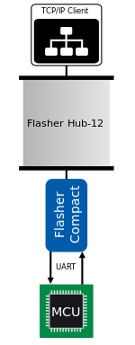
UART Port, formerly known as "UART Transceiver", is a feature of Flasher Hub that makes it possible to communicate with a target UART.
Usage
The UART Port can be used to communicate with a target UART for e.g.
- Running tests on the target after it was programmed
- Writing and reading calibration data on the target after it was programmed
- ...
A typical workflow that uses the UART Port looks as follows:
- Make sure the UART Port feature is active
- Configure and enable the UART Port for the desired module position
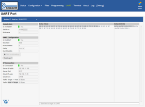
- This can be done via the terminal (see #TERMINAL command) or the web interface (see UART page)
- Open a TCP/IP connection to the UART Port
- Data sent to the UART Port via TCP/IP is forwarded to the target UART
- Data sent by the target UART is forwarded via TC/IP to the connected client
Configuration
The UART Port feature can be activated using the Config → Flasher Hub page of the web interface. The base port setting determines the port numbers that Flasher Hub will open for its modules:
Module UART Port number = Base port + Module position
For the default base port (2000), the following ports result:
| Module position | UART Port number |
|---|---|
| 1 | 2001 |
| 2 | 2002 |
| 3 | 2003 |
| [...] | [...] |
| 24 | 2024 |
Once the UART Port feature is active, UART Ports for selected modules can be enabled using
- the UART page of the web interface or
- the #TERMINAL command
UART Settings
The following list of parameters can be configured for a module's UART Port:
- Baudrate
- Number of data bits
- Parity
- Number of stop bits
UART connection
With the UART Port enabled, the target interface of the respective Flasher Compact module looks as follows:
| Pin | Signal | Type | Description |
|---|---|---|---|
| 1 | VTref | Input | Target reference voltage. It is used to create the logic-level reference for the input comparators and to control the output logic levels to the target. |
| 5 | Flasher Tx | Output | UART data: Flasher → Target |
| 17 | Flasher Rx | Input | UART data: Target → Flasher |
| 19 | V5-Supply | Output | This pin can be used to supply power to the target board. |
The voltage levels for the UART data pins are derived from the Flasher's target reference voltage, VTref.
If a voltage other than that available at the VTref pin should be used, a fixed value for VTref can be set using the #SETVTREF command.
IP Connection
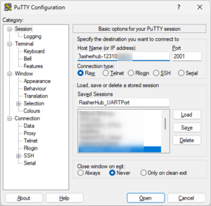
Once a modules' UART Port is enabled, a TCP/IP client can connect to it by opening a raw connection to Flasher Hub's IP address and the respective UART Port number.
Both are displayed on the UART page of the web interface for convenience.
After connecting, data sent by the client is output on the modules' UART. In the same data that is sent by the target UART is sent to the client.


