Flasher Hub - Getting started

The Flasher Hub makes ultra-fast, high-speed parallel programming ("gang programming") possible. Up to 24 Flasher Compact modules can be connected to the Flasher Hub. Each Flasher Compact module is connected to a target device.
Contents
Introduction
Via an ASCII terminal interface or handshake interface connection between the ATE (Automated Test Equipment) and the Flasher Hub, flash programming operations can be triggered and responses from the Flasher Hub can be read and evaluated. This makes the Flasher Hub a perfect fit for small-scale as well as large-scale production environments.
The firmware to be programmed into the target devices can be prepared via a computer running Windows, Linux, or macOS and SEGGER's J-Flash, J-Flash SPI or U-Flash software. The Flasher Compact modules connected to the Flasher Hub can be provisioned with the firmware to be programmed either directly via J-Flash or U-Flash, via an FTP connection to the Flasher Hub, or via the Flasher Hub's web interface.
Before putting the Flasher Hub into operation, make sure to have the following devices at hand:
- Power supply (see below for more information)
- One or more Flasher Compacts
- Ethernet cable (not mandatory)
- PC (Windows/ Linux/ macOS)
- The Flasher Hub is set up and good-to-go in less than 10 minutes
After making sure that the devices mentioned above are all available, the Flasher Hub can be setup:
- Connect Flasher Hub to power supply via the POWER connector
- Connect Flasher Hub to LAN via the LAN connector
- Connect Flasher Compact(s) to Flasher Hub via USB C
- Download and install the most recent version of the Flasher software package
- Make sure Flasher Hub is running the most recent firmware, as described below
- Open Flasher Hub's web interface by visiting
http://flasherhub-<SerialNo>/(Make sure to replace<SerialNo>with the serial number of your Flasher Hub) - Flasher Hub is now up and running
Power supply
Flasher Hub and Flasher Compact power supply
The Flasher Hub is powered via the POWER connector (pluggable terminal block) on the back panel. The power supply must be able to supply 8 - 30VDC, max. 60W to the Flasher Hub. For maximum load the power supply must provide at least 12VDC. The Flasher Compacts are powered via the USB-C connection of the Flasher Hub.

The Flasher Compacts are powered directly through the Flasher Hub they are connected to.
Current consumption (typical)
| Flasher Hub | |
|---|---|
| External DC power supply | Max. 15W |
| Flasher Compact | |
| 5V via Flasher Hub | 130 mA (no target power supply) |
| 5V via Flasher Hub | 230 mA (target power supply with 100mA) |
Undefined behavior may occur if the Flasher Hub and/or the Flasher Compacts are not powered sufficiently.
Target power supply
The target boards to be programmed can either be powered via their own power supplies, or they can be powered via a 5V / 100mA supply from the Flasher Compacts. Please refer to the Flasher Compact User Guide for details on how to do this.
Setting up the IP interface
The Flasher Hub is equipped with an Ethernet interface to communicate with the host system via your network.

The Flasher Hub also has a built-in web server that provides system status and allows system configuration.
Connecting for the first time
When connecting the Flasher Hub to your network and powering it up for the first time, it attempts to acquire an IP address via DHCP. After the Flasher Hub has finished booting (i.e. after the green LED has stopped flashing), you can connect to the Flasher Hub's web interface by pointing your web browser to
http://flasherhub-<serial_number>/
Make sure to replace <serial_number> with the serial number of your Flasher Hub, which can be found on the housing.
The "Status" page served by the Flasher Hub's web server contains the IP address that has been assigned to the Flasher Hub by your network.

Direct Ethernet connection
Instead of connecting Flasher Hub to a network, it can be set up for a direct Ethernet connection to a computer without a network between.
For this, it is necessary to configure Flasher Hub's IP interface to use a manual IP address with the same subnet mask as the Ethernet adapter of the computer.
For a Windows 10 system, the IP address and subnet mask of an Ethernet adapter can be determined as follows:
- Connect Flasher Hub to the PC using a direct Ethernet connection
- Open the Control Panel and navigate to Network and Internet → Network and Sharing Center
- In the list of active networks, determine that of the Ethernet adapter that Flasher Hub is connected to.
- In this case, it's Ethernet 4
- Open a command prompt
- Windows key + R → "cmd"
- Enter
netsh interface ip show addresses "[Name of Ethernet adapter]"- Make sure to replace [Name of Ethernet adapter] accordingly


Now, Flasher Hub's IP interface can be configured accordingly:
- Connect Flasher Hub to the PC via USB
- This can be in parallel to the Ethernet connection
- Make sure the most recent version of the Flasher software https://www.segger.com/downloads/flasher/ is installed
- Start the Flasher Configurator
- Make sure the [firmware of Flasher Hub is up to date #Firmware_update]
- In the list of programmers connected via USB, double-click Flasher Hub to configure it
- Set the IP configuration to Manual
- Set a manual IP address that is in the same subnet as that of the Ethernet adapter of the PC
- Set the same subnet mask as that of the Ethernet adapter of the PC
- Click OK

After that, Flasher Hub is set up for a direct Ethernet connection to the PC.
Operating modes
The Flasher Hub currently can be operated via web interface or via remote-controlled mode.
Web interface
The Flasher Hub web interface is the recommended way of operating the Flasher Hub for manual operation. It provides a way to use the Flasher Hub in a production environment and control it manually, i.e. not using automation via scripts or similar. Using the extensive but intuitive graphical user interface of Flasher Hub's web server, programming operations and more can be configured, monitored and controlled with ease.
The web interface is described in more detail in #Web server.
Remote-controlled mode
The remote-controlled mode provides two ways to integrate the Flasher Hub into a production environment. Via the ASCII terminal interface, the Flasher Hub provides detailed status information that can be used to verify the success of the programming sequence, optimize the production setup, and identify errors. Via the handshake interface, programming can be started and the OK and Busy statuses can be checked. These two methods of operation were mainly designed for automation purposes.
In order to use a Flasher Hub based system in remote-controlled mode, the files required for programming the target need to be stored on the connected Flasher Compact modules first. This is described in #Setting up a project for the Flasher Hub.
The remote-controlled mode is described in more detail in #Remote control.
LED status indicators
The Flasher Hub uses different LEDs as indicated in the following table.
LED indicators
| LED | Status | Meaning |
|---|---|---|
| POWER | green | Flasher Hub is powered. |
| STATUS | green | Status is O.K. |
| orange/red | Status is not O.K. (Firmware error or at least one module failed programming) | |
| Module LEDs 1-12 | green | Module is connected and powered. |
Flasher Compact LED indicators
| LED | Status | Meaning |
|---|---|---|
| Ready / O.K. | GREEN short flicker |
Module is ready. |
| Ready / O.K. | GREEN slow blinking |
Flashing operation in progress:
|
| Not ready / Fail | RED constant |
a) The module is in bootloader mode. b) The most recent operation has failed. |
Storing configuration and programming data files
The configuration and programming data required to program the target devices is stored on the connected Flasher Compact modules. Each Flasher Compact module has approximately 128MB of storage available for data and configuration files.
The Flasher Compact modules can be accessed in the following ways:
- via TXP/IP or USB by using J-Flash or U-Flash software
- via an FTP client connected to the Flasher Hub's integrated FTP-server
- via the File browser in the Flasher Hub's web interface
When using J-Flash, the connected Flasher Compact modules (Module 1, Module 2, ..., Module n) can be selected via tick boxes on the "Options > Project settings > General" screen. Make sure to select the correct connection type. For TCP/IP enter the Flasher Hub's IP address (or use flasherhub-<serial_number>).

When selecting "File > Download config & data file to Flasher" from the J-Flash menu, the configuration and data file of the current J-Flash project will be downloaded to the selected Flasher Compact modules.

When using U-Flash, the connected Flasher Compact modules can be selected via tick boxes in the Flasher selection.
When using an FTP client or the file browser in the Flasher Hub's web interface, the Flasher Compact modules are accessible via subfolders named "MODULE.xxx", with xxx being the index of the associated Flasher Compact, e.g. "MODULE.001" for the Flasher Compact module with index 1.

UART Port
For documentation on Flasher Hub's UART Port, see Flasher Hub - UART Port.
Log files
The Flasher Hub keeps a log file if logging is enabled via the web interface on the "Configuration > Flasher Hub" page. The log itself can be accessed on the "Log" page.

In addition, each Flasher Compact keeps its own log file. These log files are stored in the module folder of the corresponding Flasher Compact and can be downloaded via FTP or the file browser in the Flasher Hub's web interface. For more information on the Flasher Compact log file, please refer to the Flasher User Manual (UM08022).

Firmware update
Firmware update files for both, Flasher Hub as well as Flasher Compact modules are shipped with each new release of the Flasher software package.
It is recommended to use the most recent version of the Flasher Hub firmware as newer versions may contain various improvements as well as bug fixes.
Updating Flasher Hub firmware
The Flasher Hub firmware can up updated by using the Flasher software or by using Flasher Hub's web interface.
Using Flasher software

- Make sure to download and install the most recent version of the Flasher software package
- Make sure Flasher Hub is connected to a PC via USB or IP
- Start Flasher Configurator (FlasherConfig.exe)
- Right-click on Flasher Hub
- Click "Update firmware"
- Flasher Configurator will now update the firmware of Flasher Hub
Using Flasher Hub web interface
- Make sure to download and install the most recent version of the Flasher software package
- Make sure Flasher Hub is connected to LAN
- Open Flasher Hub's web interface by visiting
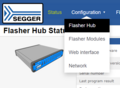
http://flasherhub-<SerialNo>/(Make sure to replace<SerialNo>with the serial number of your Flasher Hub) - Navigate to Configuration > Flasher Hub
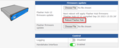
- Next to Flasher Hub firmware update click Choose file
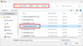
- Navigate to the installation folder of the Flasher software (e.g. C:\Program Files\SEGGER\Flasher)
- Inside the "Firmwares" folder, select the FlasherHub_V1.bin
- Click Open
- Click Upload
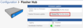
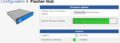
- Wait for the firmware update file to be processed by Flasher Hub
- Reboot Flasher Hub to apply the firmware update
Web interface Configuration > Flasher Hub
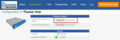
Web interface firmware update file upload
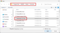
Selection of Flasher Hub firmware file
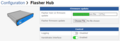
Flasher Hub processing a firmware update file
Web interface following a successful firmware update file upload


Updating module firmware
The firmware of modules connected to the Flasher Hub can be updated as follows.
- Make sure to download and install the most recent version of the Flasher software package
- Make sure Flasher Hub is connected to LAN
- Open Flasher Hub's web interface by visiting
http://flasherhub-<SerialNo>/(Make sure to replace<SerialNo>with the serial number of your Flasher Hub) - Navigate to Configuration > Flasher Hub
- Next to Flasher firmware update click Choose file
- Navigate to the installation folder of the Flasher software (e.g. C:\Program Files\SEGGER\Flasher)
- Inside the "Firmwares" folder, select the Flasher_Compact_V*.bin
- Click Open
- Click Upload
- Wait for the firmware update file to be processed by Flasher Hub
- Navigate to Status
- In the table below Module Status, select the modules to apply the firmware update to
- Click Update firmwares
Web interface Configuration > Flasher Hub
Web interface module firmware update file upload
Selection of Flasher Hub module firmware file
Flasher Hub processing a module firmware update file
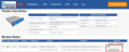
Web interface Status

Web interface while module firmware update is applied

Newline encoding
In general, for all patch files, init files etc., the Flasher Compact modules support both newline encodings:
- Windows: \r\n
- Unix/Mac: \n
All parser functionality etc. are written to be independent from the host operating system. [[Category:Flasher Hub-12]