Difference between revisions of "IS2083 Getting Started"
(→2-wire JTAG connection) |
(→Setup) |
||
| (57 intermediate revisions by 3 users not shown) | |||
| Line 1: | Line 1: | ||
| + | The IS2083 series is an 8051 based device from Microchip that is designed for low power Bluetooth applications. |
||
| + | |||
__TOC__ |
__TOC__ |
||
| − | = |
+ | = J-Link support = |
| + | J-Link supports the Microchip IS2083 series devices. For an overview which min. hardware of J-Link is required for support, please refer to the [[Software and Hardware Features Overview | feature overview]]. |
||
| − | J-link uses the Microchip 2-wire JTAG protocol to communicate with the IS208x MCU. This protocol specifies 5 pins, which are all mandatory to connect: |
||
| + | |||
| − | * RESET (mandatory to enable 2-wire JTAG protocol on the IS208x) |
||
| + | = Hardware connection to BM83 EVB = |
||
| + | J-Link uses the Microchip 2-wire JTAG protocol to communicate with the IS2083 MCU. This protocol specifies the following pins which are all mandatory to connect: |
||
| + | * RESET (mandatory to enable 2-wire JTAG protocol on the IS2083) |
||
* VTref (used as reference voltage by J-Link to adapt to different CPU operating voltages) |
* VTref (used as reference voltage by J-Link to adapt to different CPU operating voltages) |
||
* GND |
* GND |
||
| Line 9: | Line 14: | ||
* clock (provided by J-Link) |
* clock (provided by J-Link) |
||
| − | On the BM8x EVB connector J301 is used to connect J-Link to the |
+ | On the BM8x EVB connector J301 is used to connect J-Link to the IS2083 MCU. |
| + | |||
| + | We recommend to use the [https://www.segger.com/products/debug-probes/j-link/accessories/adapters/microchip-2-wire-jtag-tdi-adapter/ J-Link Microchip 2-Wire JTAG TDI Adapter] to connect J-Link to J301. |
||
| + | |||
{| class="wikitable" |
{| class="wikitable" |
||
|- |
|- |
||
| Line 25: | Line 33: | ||
|} |
|} |
||
| + | [[File:BT5511_BoardConnector.png|none]] |
||
| − | PIC |
||
| − | |||
| − | PIC |
||
= Verifying connection with J-Link Commander = |
= Verifying connection with J-Link Commander = |
||
| − | J-Link Commander (JLink.exe from the J-Link package) can be used to verify the connection between J-Link and the |
+ | J-Link Commander (JLink.exe from the J-Link package) can be used to verify the connection between J-Link and the IS2083 device. |
| − | * Download the J-Link package: [ |
+ | * Download the J-Link IS2083 package: [[Media:JLink_IS208x_Keil_Package.zip | Download]] |
| − | * Start JLink.exe |
+ | * Start J-Link Commander (JLink.exe) |
[[File:BT5511_JLinkCommander.png|none]] |
[[File:BT5511_JLinkCommander.png|none]] |
||
| − | = |
+ | = Supported IDEs and debuggers = |
| + | Currently, the IS2083 is only supported in J-Link Commander and Keil uVision for PK51. Other utilities (J-Flash, ...) / IDEs etc. do not support this device series. |
||
| + | = Debugging with Keil C51 tools = |
||
| − | == Video == |
||
| − | The following shows a short video that demonstrates debugging with J-Link under Keil PK51 tools. |
||
| − | |||
| − | [https://download.segger.com/Alex/tmp/BT5511/KeilPK51_JLinkDebugging.mp4 View] |
||
== Setup == |
== Setup == |
||
| − | * Download and install Keil PK51 tools V9.59 [https:// |
+ | * Download and install Keil C51/PK51 tools V9.59 or later: [https://www.keil.com/download/product/ Download] |
| − | * Download the J-Link |
+ | * Download the latest J-Link software from our website (to make sure that the USB drivers etc. are installed): [https://www.segger.com/downloads/jlink/ Download] |
| + | * Download the J-Link IS2083 Keil package: [[Media:JLinkIS2083_6.44.4.zip | JLinkIS2083_6.44.4.zip]] |
||
| − | * Go to Keil installation directory |
||
| + | * Make sure uVision is <b>NOT</b> started before continuing |
||
| − | |||
| − | [[File:KeilPK51_InstallDir.png|none]] |
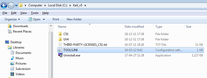
+ | * Go to Keil installation directory [[File:KeilPK51_InstallDir.png|none]] |
| + | * Open TOOLS.INI in text editor and add the following line (if TDRV10 already exists, use the next available number/entry): <syntaxhighlight lang="text">TDRV10=BIN\JLinkIS2083.dll ("J-Link / J-Trace IS2083 Driver")</syntaxhighlight> [[File:KeilPK51_ToolsINI_Edit.png|none]] |
||
| − | * Make sure uVision is <b>NOT</b> started before continuing. |
||
| − | * Open TOOLS.INI in text editor and add the following line: |
||
| − | <syntaxhighlight lang="text">TDRV10=BIN\JLinkBT5511.dll ("J-Link / J-Trace BT5511 Driver")</syntaxhighlight> |
||
| − | |||
| − | [[File:KeilPK51_ToolsINI_Edit.png|none]] |
||
| − | |||
| − | * Navigate to BIN\ |
||
| − | |||
| − | [[File:KeilPK51_BINDir.png|none]] |
||
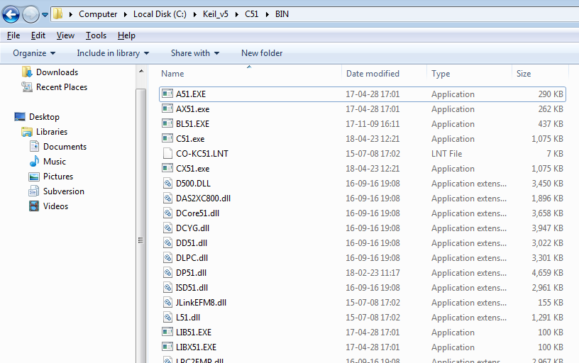
| + | * Navigate to BIN\ [[File:KeilPK51_BINDir.png|none]] |
||
* Copy the following files from the J-Link package to this directory: |
* Copy the following files from the J-Link package to this directory: |
||
| − | ** |
+ | ** JLinkIS2083.dll |
| − | ** JLinkARM.dll |
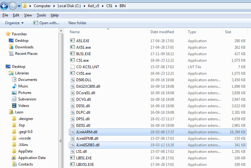
+ | ** JLinkARM.dll [[File:KeilPK51_BINDir_After.png|none]] |
| − | == |
+ | == Debug session == |
| − | * Connect |
+ | * Connect to the PC |
| − | * Wait until the green LED becomes steady and stops blinking |
+ | * Wait until the green LED of J-Link becomes steady and stops blinking |
| + | * Download the Microchip BM83 SDK application sample project from Microchip |
||
| − | * Download the uVision test project: [https://download.segger.com/Alex/tmp/BT5511/JLink_TestProject.zip Download] |
||
| + | * Make sure that you followed the initial preparation steps for the BM83x EVB from Microchip (flashing of initial image + DSP config etc.) |
||
| − | * Open the uVision test project |
||
| + | * Open project in uVision |
||
* Go to the project options |
* Go to the project options |
||
* Verify that your options look like as follows: |
* Verify that your options look like as follows: |
||
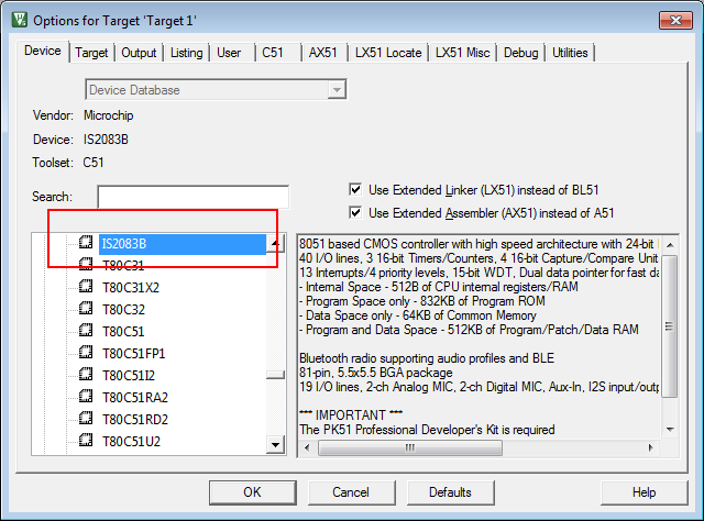
| − | * 'Device' tab: |
+ | * 'Device' tab: [[File:KeilPK51_BT5511_Options_Device.png|none]] |
| − | [[File: |
+ | * 'Debug' tab: [[File:KeilPK51_BT5511_Options_Debug.png|none]] |
| + | * Click on 'Settings' [[File:KeilPK51_BT5511_Options_Debug_Use.png|none]] |
||
| − | * 'Debug' tab: |
||
| − | [[File: |
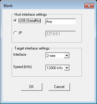
+ | * 'Settings' dialog [[File:KeilPK51_BT5511_Options_JLink.png|none]] |
| + | * Connect your target HW to J-Link via [https://www.segger.com/products/debug-probes/j-link/accessories/adapters/microchip-2-wire-jtag-tdi-adapter/ J-Link Microchip 2-wire JTAG TDI adapter] |
||
| − | * Click on 'Settings' |
||
| + | * Rebuild the application (Project -> Rebuild all target files) |
||
| − | [[File:KeilPK51_BT5511_Options_Debug_Use.png|none]] |
||
| + | * Start a debug session by clicking the "debug" symbol (Ctrl + F5)<sup>1</sup> |
||
| − | * 'Settings' dialog |
||
| − | [[File:KeilPK51_BT5511_Options_JLink.png|none]] |
||
| − | * Connect your target HW to J-Link (via 2-wire JTAG) |
||
| − | * Rebuild your application (Project -> Rebuild all target files) |
||
| − | * Start a debug session by clicking the <PiC> symbol (Ctrl + F5) |
||
| − | [[File:KeilPK51_PiC_Symbol.png|none]] |
||
| − | * 2-wire JTAG is the default selection for a J-Link BT5511 project |
||
| − | * You will be asked if you want to update the firmware of the connected J-Link. Select <b>YES</b>. |
||
* Happy debugging! |
* Happy debugging! |
||
| + | <sup>1</sup> If you are asked if you want to update the J-Link firmware, please hit <b>YES</b>. |
||
Latest revision as of 11:04, 6 August 2019
The IS2083 series is an 8051 based device from Microchip that is designed for low power Bluetooth applications.
Contents
J-Link support
J-Link supports the Microchip IS2083 series devices. For an overview which min. hardware of J-Link is required for support, please refer to the feature overview.
Hardware connection to BM83 EVB
J-Link uses the Microchip 2-wire JTAG protocol to communicate with the IS2083 MCU. This protocol specifies the following pins which are all mandatory to connect:
- RESET (mandatory to enable 2-wire JTAG protocol on the IS2083)
- VTref (used as reference voltage by J-Link to adapt to different CPU operating voltages)
- GND
- bi-directional data pin
- clock (provided by J-Link)
On the BM8x EVB connector J301 is used to connect J-Link to the IS2083 MCU.
We recommend to use the J-Link Microchip 2-Wire JTAG TDI Adapter to connect J-Link to J301.
| J301 pin | J-Link pin |
|---|---|
| 1 | 15 (RESET, blue) |
| 2 | 1 (VTref, red) |
| 3 | 4 (GND, black) |
| 4 | 5 (TDI, green) |
| 5 | 9 (TCK, yellow) |

Verifying connection with J-Link Commander
J-Link Commander (JLink.exe from the J-Link package) can be used to verify the connection between J-Link and the IS2083 device.
- Download the J-Link IS2083 package: Download
- Start J-Link Commander (JLink.exe)

Supported IDEs and debuggers
Currently, the IS2083 is only supported in J-Link Commander and Keil uVision for PK51. Other utilities (J-Flash, ...) / IDEs etc. do not support this device series.
Debugging with Keil C51 tools
Setup
- Download and install Keil C51/PK51 tools V9.59 or later: Download
- Download the latest J-Link software from our website (to make sure that the USB drivers etc. are installed): Download
- Download the J-Link IS2083 Keil package: JLinkIS2083_6.44.4.zip
- Make sure uVision is NOT started before continuing
- Go to Keil installation directory
- Open TOOLS.INI in text editor and add the following line (if TDRV10 already exists, use the next available number/entry):
TDRV10=BIN\JLinkIS2083.dll ("J-Link / J-Trace IS2083 Driver")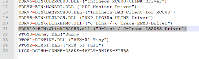


- Navigate to BIN\
- Copy the following files from the J-Link package to this directory:
- JLinkIS2083.dll
- JLinkARM.dll


Debug session
- Connect to the PC
- Wait until the green LED of J-Link becomes steady and stops blinking
- Download the Microchip BM83 SDK application sample project from Microchip
- Make sure that you followed the initial preparation steps for the BM83x EVB from Microchip (flashing of initial image + DSP config etc.)
- Open project in uVision
- Go to the project options
- Verify that your options look like as follows:
- 'Device' tab:
- 'Debug' tab:
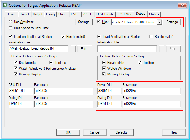
- Click on 'Settings'

- 'Settings' dialog
- Connect your target HW to J-Link via J-Link Microchip 2-wire JTAG TDI adapter
- Rebuild the application (Project -> Rebuild all target files)
- Start a debug session by clicking the "debug" symbol (Ctrl + F5)1
- Happy debugging!


1 If you are asked if you want to update the J-Link firmware, please hit YES.