Difference between revisions of "NXP LPCXpresso860-MAX"
| Line 1: | Line 1: | ||
| − | TBD |
||
| − | <!-- |
||
[[File:NXP_LPCXpresso860-MAX.jpg|thumb|450px|right|NXP LPCXpresso860-MAX evaluation board top side view]] |
[[File:NXP_LPCXpresso860-MAX.jpg|thumb|450px|right|NXP LPCXpresso860-MAX evaluation board top side view]] |
||
This article describes specifics for the NXP LPCXpresso860-MAX evaluation board. |
This article describes specifics for the NXP LPCXpresso860-MAX evaluation board. |
||
| Line 22: | Line 20: | ||
*Embedded Studio: V7.10a |
*Embedded Studio: V7.10a |
||
*Link: [[File:VENDOR_DEVICENAME_TestProject_ES_V452b.zip]] |
*Link: [[File:VENDOR_DEVICENAME_TestProject_ES_V452b.zip]] |
||
| − | --> |
||
Latest revision as of 10:40, 20 September 2023

This article describes specifics for the NXP LPCXpresso860-MAX evaluation board.
Contents
Preparing for J-Link
- Connect the J-Link to J7 using the 9-Pin Cortex-M Adapter
- Power the board via micro USB (J4)
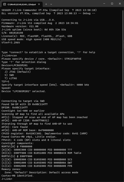
- Verify the Connection with e.g. with J-Link Commander. The output should look as follows:

Example Project
TBD -->