Difference between revisions of "NuTiny-SDK-NUC029"
(Created page with " right | thumb | Nuvoton NuTiny-SDK-NUC029LAN_V1.1 This article covers the Nuvoton NuTiny-SDK-NUC029 evaluation board. __TOC__ ==Connecting J-...") |
|||
| Line 1: | Line 1: | ||
| − | [[File:NuTiny-SDK-NUC029.png | right | thumb | Nuvoton NuTiny-SDK-NUC029LAN_V1.1]] |
+ | [[File:NuTiny-SDK-NUC029.png | right | thumb | 600px | Nuvoton NuTiny-SDK-NUC029LAN_V1.1]] |
This article covers the Nuvoton NuTiny-SDK-NUC029 evaluation board. |
This article covers the Nuvoton NuTiny-SDK-NUC029 evaluation board. |
||
__TOC__ |
__TOC__ |
||
Latest revision as of 17:33, 4 January 2021
This article covers the Nuvoton NuTiny-SDK-NUC029 evaluation board.
Contents
Connecting J-Link to the board
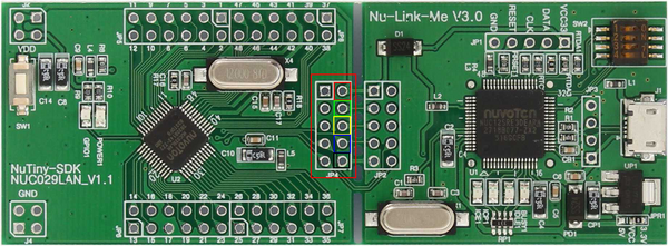
The Nuvoton NuTiny-SDK-NUC029 board does not come with an external debug connector. Therefore in order to use an external debug probe like the J-Link the Nuvoton NuTiny-SDK-NUC029 board needs to be setup manually: JP4 is soldered and can be connected as follows to J-Link
- Populate the header JP4 (Marked red in attached picture) with a 1 x 5 pin header by soldering
- Connect your JLink debug probe with e.g. jumper wires with header JP4 like described in the following table and attached connector picture (Pin 1 is marked with a white square):
| Pin header JP4 | J-Link |
|---|---|
| Pin 2 TICEVCC (RED) | Pin 1 (VTref) |
| Pin 4 TICEDAT (GREEN) | Pin 7 (SWDIO) |
| Pin 6 TICECLK (YELLOW) | Pin 6 (TICECLK) |
| Pin 8 TICERST (BLUE) | Pin 8 (TICERST) |
| Pin 10 GND (BLACK) | Pin 10 (GND) |
