NuvoTon NuMaker-EVB-KM1M7

This article describes specifics for the NuvoTon NuMaker-EVB-KM1M7 evaluation board. It can be used to test & verify NuvoTon KM1M7AF device support.
Contents
Minimum requirements
- J-Link software V7.96c or later
Preparing for J-Link
- Connect the J-Link to the SWD header (ETM1).
- Power the board via the USB jack of the break out board.
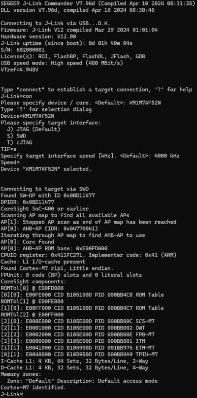
- Verify the Connection with e.g. J-Link Commander. The output should look as follows:

Example Project
The following example project was created with the SEGGER Embedded Studio project wizard and runs out-of-the-box on the NuvoTon NuMaker-EVB-KM1M7. It is a simple Hello World sample linked into the internal flash.
SETUP
- J-Link software: V7.96c
- Embedded Studio: V8.10
- Hardware: NuvoTon NuMaker-EVB-KM1M7
- Link: File:NuvoTon NuMaker-EVB-KM1M7 TestProject ES 8V10.zip
Tracing on KM1M7AF
This section describes how to get started with trace on the Nuvoton KM1M7AF MCUs. This section assumes that there is already a basic knowledge about trace in general (what is trace, what different implementations of trace are there, etc.). If this is not the case, we recommend to read Trace chapter in the J-Link User Manual (UM08001).
- The sample projects come with a pre-configured project file for Ozone that runs out-of-the box.
- The following sample project is designed to be used with J-Trace PRO for streaming trace and Ozone to demonstrate streaming trace.
- In order to rebuild the sample project, SEGGER Embedded Studio can be used.
- The examples are shipped with a compiled .JLinkScriptfile, should you need the original source, please get in touch with SEGGER directly via our support system: https://www.segger.com/ticket/.
- To create your own .JLinkScriptfile you can use the following guide as reference: How_to_configure_JLinkScript_files_to_enable_tracing
Minimum requirements
In order to use trace on the Nuvoton KM1M7AF MCU devices, the following minimum requirements have to be met:
- J-Link software version V7.96f or later
- Ozone V3.32a or later (if streaming trace and / or the sample project from below shall be used)
- J-Trace PRO for Cortex-M HW version V3.0 or later for streaming trace
To rebuild the project our IDE Embedded Studio can be used. The recommended version to rebuild the projects is V6.30. But the examples are all prebuild and work out-of-the box with Ozone, so rebuilding is not necessary.
Streaming trace
The project below has been tested with the minimum requirements mentioned above and a NuvoTon NuMaker-EVB-KM1M7.
- Example project: Nuvoton_KM1M7AF52N_Trace.zip
Specifics/Limitations
The trace signals output by the KM1M7AF do not follow the signal specification which can cause sampling issues. This can be mitigated as described here.
Reference trace signal quality
The following pictures show oscilloscope measurements of trace signals output by the "Tested Hardware" using the example project. All measurements have been performed using a Agilent InfiniiVision DSO7034B 350 MHz 2GSa/s oscilloscope and 1156A 1.5 GHz Active Probes. If your trace signals look similar on your trace hardware, chances are good that tracing will work out-of-the-box using the example project. More information about correct trace timing can be found at the following website.
Trace clock signal quality
The trace clock signal quality shows multiple trace clock cycles on the tested hardware as reference.

Rise time
The rise time of a signal shows the time needed for a signal to rise from logical 0 to logical 1. For this the values at 10% and 90% of the expected voltage level get used as markers. The following picture shows such a measurement for the trace clock signal.

Setup time
The setup time shows the relative setup time between a trace data signal and trace clock. The measurement markers are set at 50% of the expected voltage level respectively. The following picture shows such a measurement for the trace data signal 0 relative to the trace clock signal.
