Difference between revisions of "Renesas RZ/T2M-RSK"
(→Preparing for J-Link) |
(→Example Project) |
||
| Line 14: | Line 14: | ||
[[File:Renesas_RZT2M_Connect.PNG|400px]] |
[[File:Renesas_RZT2M_Connect.PNG|400px]] |
||
| + | |||
| + | == Preperation NOR flash programming== |
||
| + | #Check whether SW4 on RZ/T2M RSK board is set as 16bit bus boot mode(NOR flash):<br>'''<SW4>''' (16bit bus boot mode (NOR flash))<br>1-OFF; 2-ON; 3-ON; 4-OFF; 5-OFF; 6-ON; 7-OFF; 8-ON; 9-ON; 10-OFF |
||
| + | #Push red reset button of RZ/T2M RSK board. |
||
| + | |||
| + | |||
== Example Project== |
== Example Project== |
||
Revision as of 10:24, 30 August 2022
Contents
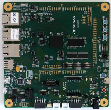
This article describes specifics for the Renesas RZ/T2M-RSK evaluation board.
Minimum requirements
- J-Link software V7.68 or later
Preparing for J-Link
- Connect the J-Link to the debug header (J13 or J20)
- Power the board via USB C (CN5) or external power supply / power jack (CN6)
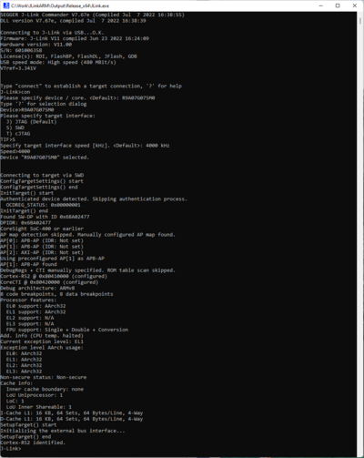
- Verify the Connection with e.g. J-Link Commander. The output should look as follows:
Preperation NOR flash programming
- Check whether SW4 on RZ/T2M RSK board is set as 16bit bus boot mode(NOR flash):
<SW4> (16bit bus boot mode (NOR flash))
1-OFF; 2-ON; 3-ON; 4-OFF; 5-OFF; 6-ON; 7-OFF; 8-ON; 9-ON; 10-OFF - Push red reset button of RZ/T2M RSK board.
Example Project
TBD
SETUP
TBD

