Difference between revisions of "TI LP-EM-CC2340R5"
(→Example Project) |
|||
| Line 11: | Line 11: | ||
== Example Project== |
== Example Project== |
||
| + | The following example application contains a small blinky application and can be used to test & verify flash programming functionality on the TI LP-EM-CC2340R5 evaluation board. It is a simple blinky linked into the internal flash and contains a valid CCFG block. |
||
| − | TBD |
||
| + | ====SETUP==== |
||
| + | *J-Link software: V7.88c |
||
| + | *Hardware: TI LP-EM-CC2340R5 |
||
| + | *Link: [[File:TI_LP_EM_CC2340R5_Blinky.zip]] |
||
Latest revision as of 09:53, 17 May 2023
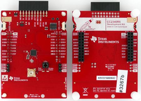
This article describes specifics for the TI LP-EM-CC2340R5 evaluation board.

Preparing for J-Link
- Connect the J-Link to J4
- Power the board via 3.3V DC (3.3V connected 3V3; GND connected to GND)
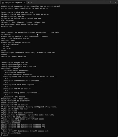
- Verify the Connection with e.g. J-Link Commander. The output should look as follows:
Example Project
The following example application contains a small blinky application and can be used to test & verify flash programming functionality on the TI LP-EM-CC2340R5 evaluation board. It is a simple blinky linked into the internal flash and contains a valid CCFG block.
SETUP
- J-Link software: V7.88c
- Hardware: TI LP-EM-CC2340R5
- Link: File:TI LP EM CC2340R5 Blinky.zip
