Difference between revisions of "TI LP-MSPM0L1306"
(Created page with "450px|thumb|right This article describes specifics for the TI LP-MSPM0L1306 evaluation board. It can be used to test & verify MSPM0L device suppo...") |
|||
| Line 1: | Line 1: | ||
| − | [[File:TI_LP-MSPM0L1306.jpg|450px|thumb|right]] |
+ | [[File:TI_LP-MSPM0L1306.jpg|450px|thumb|right|TI LP-MSPM0L1306 evaluation board]] |
This article describes specifics for the TI LP-MSPM0L1306 evaluation board. |
This article describes specifics for the TI LP-MSPM0L1306 evaluation board. |
||
It can be used to test & verify MSPM0L device support. |
It can be used to test & verify MSPM0L device support. |
||
Latest revision as of 11:08, 16 November 2022

This article describes specifics for the TI LP-MSPM0L1306 evaluation board. It can be used to test & verify MSPM0L device support.
Minimum requirements
- J-Link software V7.68 or later
Preparing for J-Link
- Remove all but the first three left jumpers of J101
- Connect the J-Link to the SWD header (J103)
- Power the board via the USB jack of the break out board.
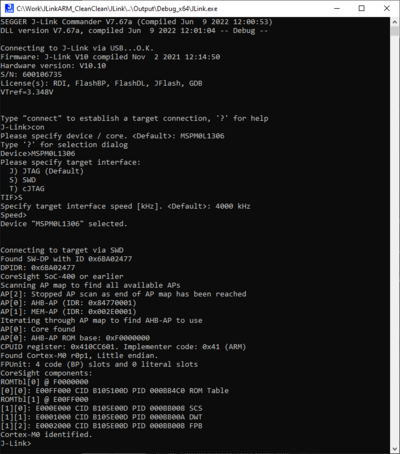
- Verify the Connection with e.g. J-Link Commander. The output should look as follows:

Example Project
The following example project was created with the SEGGER Embedded Studio project wizard and runs out-of-the-box on the TI LP-MSPM0L1306. It is a simple Hello World sample linked into the internal flash.
SETUP
- J-Link software: V7.68
- Embedded Studio: V6.30
- Hardware: TI LP-MSPM0L1306
- Link: File:TI MSPM0L1306 TestProject ES V630.zip