UM08043 Flasher Hub-12

Contents
- 1 Introduction
- 2 Getting Started
- 3 Setting up a project for the Flasher Hub-12
- 4 Serial number handling
- 5 Patch data file
- 6 FTP server
- 7 Web server
- 8 Module terminal server
- 9 Remote control
- 9.1 ASCII terminal interface
- 9.1.1 Introduction
- 9.1.2 Setting up an ASCII terminal connection
- 9.1.3 General command and reply message format
- 9.1.4 General usage
- 9.1.5 Commands
- 9.1.5.1 Command #AUTO
- 9.1.5.2 Command #AUTO NOPATCH
- 9.1.5.3 Command #AUTO PATCH
- 9.1.5.4 Command #BAUDRATE
- 9.1.5.5 Command #CANCEL
- 9.1.5.6 Command #ERASE
- 9.1.5.7 Command #FFORMAT
- 9.1.5.8 Command #FWVERSION
- 9.1.5.9 Command #FWVERSIONMOD
- 9.1.5.10 Command #IPCONFIG
- 9.1.5.11 Command #POWERON
- 9.1.5.12 Command #POWEROFF
- 9.1.5.13 Command #PROGRAM
- 9.1.5.14 Command #PROJECT
- 9.1.5.15 Command #PROTVER
- 9.1.5.16 Command #RESETIPCONFIG
- 9.1.5.17 Command #RESULT
- 9.1.5.18 Command #RTTOFF
- 9.1.5.19 Command #RTTON
- 9.1.5.20 Command #SELECT
- 9.1.5.21 Command #SELMODULE
- 9.1.5.22 Command #SERIAL
- 9.1.5.23 Command #SERIALMOD
- 9.1.5.24 Command #SETVTREF
- 9.1.5.25 Command #START
- 9.1.5.26 Command #STATUS
- 9.1.5.27 Command #TERMINAL
- 9.1.5.28 Command #VERIFY
- 9.1.6 Replies from the Flasher Hub-12
- 9.2 Handshake interface
- 9.1 ASCII terminal interface
- 10 Support and FAQs
- 11 Mechanics
- 12 Literature and references
Introduction
Overview
SEGGER's Flasher Hub-12 is a Control Module for parallel programming.
The Flasher Hub-12 is able to control up to 12 Flasher Compact modules serving as individual channels for parallel, high-speed gang-programming. If required, each channel can be configured to program a different device with a different firmware image.
The Flasher Compact modules connected to the Flasher Hub-12 are set up just once per channel configuration using SEGGER's Flasher software package. The software to be used depends on the type of flash chip being programmed. The Flasher Hub-12 can receive commands and send results via the ASCII terminal interface "stand-alone", without the need of a desktop PC. The combination of a single Flasher Hub-12 and multiple Flasher Compact modules is the perfect solution for high-volume mass production.
The Flasher Hub-12 supports all flash devices and programming interfaces supported by the Flasher Compact. By using Flasher Compacts as the programming modules, the Flasher Hub-12 takes advantage of the extensive list of supported devices and target interfaces, plus the ultra-fast programming speed and reliability of these 'Almost-Anything'-Programmers.
Features of the Flasher Hub-12
- Stand-alone In-System Programming (ISP) hub
- Scalable solution with up to 12 supported individual parallel programming channels, each with their own programming circuit memory
- Built-in web & FTP servers for easy setup
Working environment
General
The Flasher Hub-12 has been designed to be used in conjunction with automated test equipment (ATE).
It is modular and scalable from 1 to 12 individual programming modules, represented by SEGGER Flasher Compacts.
The Flasher Compacts are connected directly to and powered via the Flasher Hub-12.

Flasher PC-software (J-Flash/J-Flash SPI/U-Flash)
In order to prepare the firmware/data to be programmed to the targets and download it to the Flasher Compacts, the latest version of the J-Flash (JFlash.exe), J-Flash SPI (JFlashSPI.exe) or U-Flash (UniversalFlasher.exe) software is required.
J-Flash, J-Flash SPI and U-Flash are available for Windows, Linux, and macOS, and are part of the Flasher software and documentation package, which can be downloaded from our website:
https://www.segger.com/downloads/flasher/#FlasherSoftwareAndDocumentationPack
For more information about using J-Flash, please refer to the J-Flash User Manual (UM08003).
J-Flash SPI is described in the J-Link / J-Trace User Guide (UM08001).
And for information about U-Flash, please refer to the U-Flash User Manual (UM08037).
FTP Client
The firmware to be programmed to the targets can also be uploaded to the Flasher Compacts via an FTP connection to the Flasher Hub-12.
For this, an FTP client is required.
Web Browser
The Flasher Hub-12's web interface offers useful status information about the system.
It also allows firmware updates to the Flasher Hub-12 and the connected Flasher Compacts, uploading the firmware to be programmed to the targets, configuring the index of the connected Flasher Compact modules, and more.
In order to access the Flasher Hub-12 web interface, a web browser is required.
Terminal program
For communication with the Flasher Hub-12 via the ASCII terminal interface, a terminal program like TeraTerm or PuTTY is helpful.
Specifications
| Specifications | |
|---|---|
| Power supply | 8-30VDC, reverse polarity protected, max. 60W[1] |
| Power consumption | Max. 15W |
| USB Flasher interface | USB-C 2.0 |
| Host interfaces | USB Type-B (Upstream), USB Type-A (Downstream), Ethernet, RS232 9-pin |
| Operating Temperature | +5°C ... +60°C |
| Storage Temperature | -20°C ... +65°C |
| Relative Humidity (non-condensing) | < 90% rH |
| Size (without cables) | 170mm x 172mm x 35mm |
| Weight (without cables) | 660g |
- ↑ Depends on current consumption of connected downstream devices. For maximum load the input supply must provide 12 VDC or more.
Supported CPU cores
The Flasher Hub-12 itself is CPU-core agnostic. The supported CPU cores are determined by the connected Flasher Compacts. Please see the Flasher Compact User Guide for details.
Supported Target interfaces
The Flasher Hub-12 itself is target-interface agnostic. The supported target interfaces are determined by the connected Flasher Compacts. Please see the Flasher Compact User Guide for details.
Getting Started
The Flasher Hub-12 makes ultra-fast, high-speed parallel programming ("gang programming") possible. Up to 12 Flasher Compact modules can be connected to the Flasher Hub-12. Each Flasher Compact module is connected to a target device.

Via an ASCII terminal interface or handshake interface connection between the ATE (Automated Test Equipment) and the Flasher Hub-12, flash programming operations can be triggered and responses from the Flasher Hub-12 can be read and evaluated. This makes the Flasher Hub-12 a perfect fit for small-scale as well as large-scale production environments.
The firmware to be programmed into the target devices can be prepared via a computer running Windows, Linux, or macOS and SEGGER's J-Flash, J-Flash SPI or U-Flash software. The Flasher Compact modules connected to the Flasher Hub-12 can be provisioned with the firmware to be programmed either directly via J-Flash or U-Flash, via an FTP connection to the Flasher Hub-12, or via the Flasher Hub-12's web interface.
Before putting the Flasher Hub-12 into operation, make sure to have the following devices at hand:
- Power supply (see below for more information)
- One or more Flasher Compacts
- Ethernet cable (not mandatory)
- PC (Windows/ Linux/ macOS)
- The Flasher Hub-12 is set up and good-to-go in less than 10 minutes
After making sure that the devices mentioned above are all available, the Flasher Hub-12 can be setup:
- Connect Flasher Hub-12 to power supply via the POWER connector
- Connect Flasher Hub-12 to LAN via the LAN connector
- Connect Flasher Compact(s) to Flasher Hub-12 via USB C
- Download and install the most recent version of the Flasher software package
- Make sure Flasher Hub-12 is running the most recent firmware, as described below
- Open Flasher Hub-12's web interface by visiting
http://flasherhub-<SerialNo>/(Make sure to replace<SerialNo>with the serial number of your Flasher Hub-12) - Flasher Hub-12 is now up and running
Power supply
Flasher Hub-12 and Flasher Compact power supply
The Flasher Hub-12 is powered via the POWER connector (pluggable terminal block) on the back panel. The power supply must be able to supply 8 - 30VDC, max. 60W to the Flasher Hub-12. For maximum load the power supply must provide at least 12VDC. The Flasher Compacts are powered via the USB-C connection of the Flasher Hub-12.

The Flasher Compacts are powered directly through the Flasher Hub-12 they are connected to.
Current consumption (typical)
| Flasher Hub-12 | |
|---|---|
| External DC power supply | Max. 15W |
| Flasher Compact | |
| 5V via Flasher Hub-12 | 130 mA (no target power supply) |
| 5V via Flasher Hub-12 | 230 mA (target power supply with 100mA) |
Undefined behavior may occur if the Flasher Hub-12 and/or the Flasher Compacts are not powered sufficiently.
Target power supply
The target boards to be programmed can either be powered via their own power supplies, or they can be powered via a 5V / 100mA supply from the Flasher Compacts. Please refer to the Flasher Compact User Guide for details on how to do this.
Setting up the IP interface
The Flasher Hub-12 is equipped with an Ethernet interface to communicate with the host system via your network.

The Flasher Hub-12 also has a built-in web server that provides system status and allows system configuration.
Connecting for the first time
When connecting the Flasher Hub-12 to your network and powering it up for the first time, it attempts to acquire an IP address via DHCP. After the Flasher Hub-12 has finished booting (i.e. after the green LED has stopped flashing), you can connect to the Flasher Hub-12's web interface by pointing your web browser to
http://flasherhub-<serial_number>/
Make sure to replace <serial_number> with the serial number of your Flasher Hub-12, which can be found on the housing.
The "Status" page served by the Flasher Hub-12's web server contains the IP address that has been assigned to the Flasher Hub-12 by your network.

Don't connect the Flasher Hub-12 directly to the Ethernet interface of an ATE or host computer. Only connect the Flasher Hub-12 to your network via a router, switch, etc.
Operating modes
The Flasher Hub currently can be operated via web interface or via remote-controlled mode.
Web interface
The Flasher Hub-12 web interface is the recommended way of operating the Flasher Hub-12 for manual operation. It provides a way to use the Flasher Hub-12 in a production environment and control it manually, i.e. not using automation via scripts or similar. Using the extensive but intuitive graphical user interface of Flasher Hub-12's web server, programming operations and more can be configured, monitored and controlled with ease.
The web interface is described in more detail in #Web server.
Remote-controlled mode
The remote-controlled mode provides two ways to integrate the Flasher Hub-12 into a production environment. Via the ASCII terminal interface, the Flasher Hub-12 provides detailed status information that can be used to verify the success of the programming sequence, optimize the production setup, and identify errors. Via the handshake interface, programming can be started and the OK and Busy statuses can be checked. These two methods of operation were mainly designed for automation purposes.
In order to use a Flasher Hub-12 based system in remote-controlled mode, the files required for programming the target need to be stored on the connected Flasher Compact modules first. This is described in #Setting up a project for the Flasher Hub-12.
The remote-controlled mode is described in more detail in #Remote control.
LED status indicators
The Flasher Hub-12 uses different LEDs as indicated in the following table.
LED indicators
| LED | Status | Meaning |
|---|---|---|
| POWER | green | Flasher Hub-12 is powered. |
| STATUS | green | Status is O.K. |
| orange/red | Status is not O.K. (Firmware error or at least one module failed programming) | |
| Module LEDs 1-12 | green | Module is connected and powered. |
Flasher Compact LED indicators
| LED | Status | Meaning |
|---|---|---|
| Ready / O.K. | GREEN short flicker |
Module is ready. |
| Ready / O.K. | GREEN slow blinking |
Flashing operation in progress:
|
| Not ready / Fail | RED constant |
a) The module is in bootloader mode. b) The most recent operation has failed. |
Storing configuration and programming data files
The configuration and programming data required to program the target devices is stored on the connected Flasher Compact modules. Each Flasher Compact module has approximately 128MB of storage available for data and configuration files.
The Flasher Compact modules can be accessed in the following ways:
- via TXP/IP or USB by using J-Flash or U-Flash software
- via an FTP client connected to the Flasher Hub-12's integrated FTP-server
- via the File browser in the Flasher Hub-12's web interface
When using J-Flash, the connected Flasher Compact modules (Module 1, Module 2, ..., Module n) can be selected via tick boxes on the "Options > Project settings > General" screen. Make sure to select the correct connection type. For TCP/IP enter the Flasher Hub-12's IP address (or use flasherhub-<serial_number>).

When selecting "File > Download config & data file to Flasher" from the J-Flash menu, the configuration and data file of the current J-Flash project will be downloaded to the selected Flasher Compact modules.

When using U-Flash, the connected Flasher Compact modules can be selected via tick boxes in the Flasher selection.
When using an FTP client or the file browser in the Flasher Hub-12's web interface, the Flasher Compact modules are accessible via subfolders named "MODULE.xxx", with xxx being the index of the associated Flasher Compact, e.g. "MODULE.001" for the Flasher Compact module with index 1.

UART to TCP transceiver
The UART Transceiver is not yet supported by the latest firmware version.
The Flasher Hub-12 features an UART to TCP transceiver: Each module is accessible via a connection to a module-specific TCP port.
| Module | TCP port |
|---|---|
| #1 | 41 |
| #2 | 42 |
| #3 | 43 |
| #4 | 44 |
| #5 | 45 |
| #6 | 46 |
| #7 | 47 |
| #8 | 48 |
| #9 | 49 |
| #10 | 50 |
| #11 | 51 |
| #12 | 52 |
If the transceiver is enabled, incoming data on pin 17 on the debug interface is sent to the TCP connection, and incoming data on the TCP connection is sent to pin 5 on the debug interface.
The transceiver can be enabled for one or more modules either via the ASCII Terminal command #TERMINAL or via the web interface "UART" page. For more information, please refer to the #TERMINAL command and the web interface "UART" page.
The transceiver cannot be enabled while the module is programming. Also programming, erasing etc. can not be started if the transceiver mode is active.
Log files
The Flasher Hub-12 keeps a log file if logging is enabled via the web interface on the "Configuration > Flasher Hub" page. The log itself can be accessed on the "Log" page.

In addition, each Flasher Compact keeps its own log file. These log files are stored in the module folder of the corresponding Flasher Compact and can be downloaded via FTP or the file browser in the Flasher Hub-12's web interface. For more information on the Flasher Compact log file, please refer to the Flasher User Manual (UM08022).

Firmware update
Firmware update files for both, Flasher Hub-12 as well as Flasher Compact modules are shipped with each new release of the Flasher software package.
It is recommended to use the most recent version of the Flasher Hub-12 firmware as newer versions may contain various improvements as well as bug fixes.
Updating Flasher Hub-12 firmware
The Flasher Hub-12 firmware can up updated by using the Flasher software or by using Flasher Hub-12's web interface.
Using Flasher software

- Make sure to download and install the most recent version of the Flasher software package
- Make sure Flasher Hub-12 is connected to a PC via USB or IP
- Start Flasher Configurator (FlasherConfig.exe)
- Right-click on Flasher Hub-12
- Click "Update firmware"
- Flasher Configurator will now update the firmware of Flasher Hub-12
Using Flasher Hub-12 web interface
- Make sure to download and install the most recent version of the Flasher software package
- Make sure Flasher Hub-12 is connected to LAN
- Open Flasher Hub-12's web interface by visiting
http://flasherhub-<SerialNo>/(Make sure to replace<SerialNo>with the serial number of your Flasher Hub-12) - Navigate to Configuration > Flasher Hub
- Next to Flasher Hub-12 firmware update click Choose file
- Navigate to the installation folder of the Flasher software (e.g. C:\Program Files\SEGGER\Flasher)
- Inside the "Firmwares" folder, select the FlasherHub-12_V1.bin
- Click Open
- Click Upload
- Wait for the firmware update file to be processed by Flasher Hub-12
- Reboot Flasher Hub to apply the firmware update
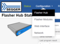
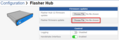
Web interface Configuration > Flasher Hub

Web interface firmware update file upload
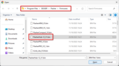
Selection of Flasher Hub-12 firmware file
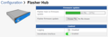
Flasher Hub-12 processing a firmware update file
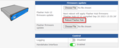
Web interface following a successful firmware update file upload


Updating module firmware
The firmware of modules connected to the Flasher Hub-12 can be updated as follows.
- Make sure to download and install the most recent version of the Flasher software package
- Make sure Flasher Hub-12 is connected to LAN
- Open Flasher Hub-12's web interface by visiting
http://flasherhub-<SerialNo>/(Make sure to replace<SerialNo>with the serial number of your Flasher Hub-12) - Navigate to Configuration > Flasher Hub
- Next to Flasher firmware update click Choose file
- Navigate to the installation folder of the Flasher software (e.g. C:\Program Files\SEGGER\Flasher)
- Inside the "Firmwares" folder, select the Flasher_Compact_V*.bin
- Click Open
- Click Upload
- Wait for the firmware update file to be processed by Flasher Hub-12
- Navigate to Status
- In the table below Module Status, select the modules to apply the firmware update to
- Click Update firmwares
Web interface Configuration > Flasher Hub
Web interface module firmware update file upload
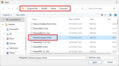
Selection of Flasher Hub-12 module firmware file
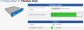
Flasher Hub-12 processing a module firmware update file
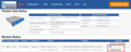
Web interface Status

Web interface while module firmware update is applied

Newline encoding
In general, for all patch files, init files etc., the Flasher Compact modules support both newline encodings:
- Windows: \r\n
- Unix/Mac: \n
All parser functionality etc. are written to be independent from the host operating system.
Setting up a project for the Flasher Hub-12
In order to set up the Flasher Hub-12 for parallel programming, the connected Flasher Compact modules need to be configured once using either J-Flash or U-Flash. Both programs are part of SEGGER's Flasher software and documentation package, available for download free of cost at:
https://www.segger.com/downloads/flasher/#FlasherSoftwareAndDocumentationPack.
Using J-Flash
J-Flash is SEGGER's desktop software for production programming and it is available for Windows, macOS and Linux. It can be used to create Flasher configuration and data files for ARM-based target devices. For more information about J-Flash, please refer to the J-Flash User Manual.
In order to set up the Flasher Hub for parallel programming, the connected Flasher Compact modules need to be configured once using J-Flash.
After starting J-Flash, open the appropriate J-Flash project for the target device the Flasher Compacts shall be configured for, by selecting File -> Open Project. If J-Flash does not come with an appropriate sample project for the desired hardware, a new project needs to be created by selecting File -> New Project.
After the appropriate project has been opened / created, the data file which shall be programmed needs to be loaded, by selecting File -> Open data file.... Next, click on Options -> Project settings -> General and select Connection type to be TCP/IP. As the TCP/IP address, enter flasherhub-<serial_number>. You can find the serial number of your Flasher Hub on the product housing.
Click Flasher Hub module selection and select the Flasher Compact module numbers you would like to configure. Then click OK.
After this, J-Flash should look similar to the screenshot below.

Next, you can transfer the necessary files to the Flasher Compacts using File -> Download config & data file to Flasher. Check the J-Flash Log window to make sure the file transfer was successful. For further details please check the J-Flash manual.
If J-Flash has trouble connecting to flasherhub-<serial_number>, use the actual IP address of your Flasher Hub. You can find the Flasher Hub-12's IP address by using the Flasher Configurator:

From now on, the Flasher Hub and the attached Flasher Compacts can be used in stand-alone mode (without host PC interaction) for stand-alone programming.
As an alternative to the process described above, you may also save the files to disk and upload them to the Flasher Compacts via the web interface. To do this, follow the instructions below:
- Save the configuration (project) file to disk by selecting File -> Save Flasher Config File
- Save the data (program data) file by selecting File -> Save Flasher Data File
- Connect to the Flasher Hub Web interface via a browser.
- Navigate to the file browser in the "Files" tab
- Now the configuration file and the data file can be uploaded to the Flasher Hub module folder(s) (MODULE.xxx), i.e. to the connected Flasher Compacts.
Choosing the All modules folder will upload the files to all Flasher Compacts connected to the Flasher Hub.
Note: The file(s) can be uploaded by dragging and dropping inside the browser window.

A third option is to upload the configuration and data files to the Flasher Compact modules via FTP as described here: #FTP server.
If J-Flash also generates a .pex file (which is a device-specific flash programming algorithm that is required for certain target devices), this also needs to be uploaded to the module folder(s) for programming to be successful. Please note that it must be located in a subfolder with the same name as your project, e.g. if your project is named MyProject with the project files MyProject.cfg and MyProject.dat, then the subfolder must be named MyProject.


Using U-Flash
The Universal Flash Loader mode can be used to program non ARM-based targets. While configurations generated with J-Flash rely on using the debug interface of the device, configurations using U-Flash make use of device or vendor specific programming interfaces and protocols and therefore it is independent of the CPU core.
A Universal Flash Loader configuration can be created using SEGGER's U-Flash, available for Windows, macOS and Linux.
For details, please see the U-Flash User Manual (UM08037) as well as the Flasher User Manual (UM08022).

Serial number handling
Serial number programming
A Flasher Hub-12 based system supports programming of serial numbers. In order to use the serial number programming feature, the J-Flash project to be used as well as some files on the Flasher Compacts connected to the Flasher Hub-12 (depending on the configuration) need to be configured first.
In general, a Flasher Hub-12 based system supports two ways of programming a serial number into the target:
-
- Programming continuous serial numbers.
- The serial number is 1-4 bytes in size.
- The start serial number, increment, serial number size, and address are configured in the J-Flash project.
-
- Programming custom serial numbers from a serial number list file.
- The start line within the serial number list file to get the next serial number bytes, line increment, serial number size, and address is configured in the J-Flash project.
- The serial number list file needs to be specified and created by the user.
Serial number settings
In order to enable the programming of serial numbers in stand-alone mode, the J-Flash project has to be configured to enable programming a serial number at a specific address. This is done by enabling the Program serial number option as shown in the screenshot and table below:

| Setting | Meaning |
|---|---|
| Address | The address the serial number should be programmed at. |
| Length |
The length of the serial number (in bytes) that should be programmed.
|
| Next SN |
|
| Increment | Specifies by how much Next SN is incremented. |
Serial number file
When selecting File -> Download serial number file to Flasher, J-Flash will create a serial number file named as <JFlashProjectName>_Serial.txt. This file is downloaded as Serial.txt on the selected Flasher Compacts connected to the Flasher Hub-12. The file is generated based on the serial number settings in the J-Flash project and will contain the value defined by the Next SN option. The serial number file can also be manually edited by the user since the serial number is written ASCII encoded in the Serial.txt file.
Continuous Serial numbers
Projects for the Flasher Hub-12 can be configured to use the serial number feature (see #Serial number settings). The serial number is stored in the Serial.txt file on each Flasher Compact module. Therefore, the serial number is also power-cycle safe. If the file is missing at start up time, a Serial.txt with serial number 0 will be created. The connected Flasher Compacts will use the current serial number found in Serial.txt for the programmed device. Then the increment is added to the serial number and the result is stored in the Serial.txt which is used for the next programming sequence.
To avoid duplication of serial numbers with the Flasher Hub-12 using more than one Flasher Compact module, there are two options:
- Use an increment of the number of connected Flasher Compact modules; e.g. if you have 5 Flasher Compacts connected, use an increment of 5 as well as 5 different Serial.txt files at the beginning of production.
- Use different serial number areas; e.g. if you have 5 Flasher Compacts connected, use an increment of 1 as well as 5 different Serial.txt files at the beginning of production. For the first module, use the range from 1 to 1000, for the second 1001 to 2000, and so on.
The Serial.txt file contains the value Next SN in ASCII notation, e.g. 1234 if the next serial number is 1234.
The serial number in Serial.txt will also be incremented if serial number programming is disabled, to make sure that for the Flasher Hub-12 log file there is a reference for which programming cycle passed and which did not. As long as serial number programming has not been enabled in the J-Flash project, the Flasher Hub-12 does not merge any serial number data into the image data to be programmed.
Serial number list file
In order to program custom serial numbers which cannot be covered by the standard serial number scheme provided by J-Flash (e.g. when programming non-continuous serial numbers or having gaps between the serial numbers), a so called serial number list file needs to be created by the user.
When selecting File -> Download serial number file to Flasher, J-Flash will look for a serial number list file named as <JFlashProjectName>_SNList.txt in the directory where the J-Flash project is located. This file is downloaded as SNList.txt on the selected Flasher Compacts connected to the Flasher Hub-12. The serial number list file needs to be created manually by the user and has the following syntax:
- One serial number per line
- Each byte of the serial number is described by two hexadecimal digits.
Example
An 8-byte serial number should be programmed at address 0x08000000.
It should be programmed as follows in the memory:
0x08000000: 0x01 0x02 0x03 0x04 0x55 0x66 0x77 0x88
The associated serial number list in the file should look as follows:

The number of bytes to read per line is configured via the Len option in J-Flash. For more information, please refer to #Serial number settings.
Which line Flasher will read at the next programming cycle is configured via the Next SN option in J-Flash. For more information, please refer to #Serial number settings. In this case, Next SN needs to be set to 0, since programming should start with the serial number bytes defined in the first line of the file.
If the number of bytes specified in a line of the serial number list file is less than the serial number length defined in the J-Flash project, the remaining bytes are filled with 0s by the Flasher Hub-12.
If the number of bytes specified in a line of the serial number list file is greater than the serial number length defined in the J-Flash project, the remaining bytes will be ignored by the Flasher Hub-12.
Programming process
The Flasher Compact modules connected to the Flasher Hub-12 will increment the serial number in Serial.txt by the value defined in Increment after each successful programming cycle.
For each programming cycle, the Flasher.log file on the connected Flasher Compact modules is updated and contains the value from Serial.txt that has been used for the programming cycle.
The serial number in Serial.txt will also be incremented if serial number programming is disabled, to make sure that for the Flasher Compact logfile there is a reference for which programming cycle passed and which did not. As long as serial number programming has not been enabled in the J-Flash project, the Flasher Compacts do not merge any serial number data into the image data to be programmed.
Example setup
Below, a small example is given on how to set up the Flasher Compacts for serial number programming. In the following example, 4-byte serial numbers starting at 1234567 (0x12D687) shall be programmed at address 0x08001000.
Defining serial number address, length and start value
In the J-Flash project, the following needs to be defined:
- Address is 0x08001000
- Next SN is 1234567
- Increment is 1
- Len is 4 (bytes)
Downloading configuration, data, and serial number to the Flasher Compacts
After setting up the rest of the configuration (Target interface etc.) and selecting an appropriate data file, the configuration,
data, and serial number file needs to be transferred to the associated Flasher Compact via the Flasher Hub-12, either using J-Flash, or using an FTP client, or using the file browser in the Flasher Hub-12's web interface.
Limiting the number of programming cycles
The Flasher Hub-12 provides a mechanism to limit the number of programming cycles that can be performed in stand-alone mode with the configuration that is stored on the Flasher Compacts. To make use of this feature, a file called Cntdown.txt needs to be placed onto the Flasher Compacts module folder. This file simply contains a decimal number (32-bit unsigned integer) that describes how many programming cycles can be performed with the current setup.

This feature especially makes sense when used in combination with authorized flashing. For more information about authorized flashing, please refer to the Flasher User Manual.
The number in Cntdown.txt is only updated on a successful programming cycle. Programming cycles that failed do not affect Cntdown.txt.
Modified fail/error LED indicator behavior
In case a Cntdown.txt is found at boot time, the fail/error LED of the Flasher Compact behaves differently. If the number of programming cycles left is 10 or below, the following will happen:
- The red error/fail LED will be lit for 1 second
- After this, it will blink/toggle x times @ 5 Hz, indicating the number of programming cycles left (blinking 5 times for 5 cycles left, etc.)
Patch data file
Patch file support
The Flasher Compact modules connected to the Flasher Hub-12 support patch files, which allows to patch the content of the data to be programmed. Before starting the programming process in stand-alone mode, the Flasher Compact module will look for a file named Patches.txt being present. This file includes the patches. If this file is present, the number in Serial.txt describes the line number of the Patches.txt file that will be used for the current cycle (line counting starts at 0).
Each line in Patches.txt can hold up to 4 patches, where each patch can be up to 32 bytes in length.
Syntax
Each line begins with <NumPatches> followed by each patch <Addr>,<NumBytes>:<Data> in sequence and separated by commas.
So the syntax for <NumPatches> = 4 would be as follows:
<NumPatches>,<Addr>,<NumBytes>:<Data>,<Addr>,<NumBytes>:<Data>,<Addr>,<NumBytes>:<Data>,<Addr>,<NumBytes>:<Data>
Find below a table which describes each parameter.
| Parameter | Description |
|---|---|
| <NumPatches> | Describes the number of patches in this patch line. Max. value is 4. |
| <Addr> | Describes the address to be patched. Value is expected in hex. |
| <NumBytes> | Number of bytes for the current patch. Max. value is 20h (32 in decimal). Value is expected in hex. |
| <Data> | Describes the data to be patched. <Data> is always expected as 2 hexadecimal characters per byte. |
All values are expected in hexadecimal format (hex).
The <Data> section is always preceded by ":", not ",".
Example
Please find below an example sequence which clarifies the usage of patch files.
Patches.txt, which is located on the Flasher Compact(s), contains the following line:
3,100025,3:AABBCC,100063,2:DDEE,100078,1:FF
Serial.txt contains a "0", which forces the Flasher Compact to use line 0 from Patches.txt.
After starting the programming cycle, the following data will be patched:
Addr 0x100025: 3 byte 0xAA 0xBB 0xCC
Addr 0x100063: 2 byte 0xDD 0xEE
Addr 0x100078: 1 byte 0xFF
Single patch via ASCII terminal
Alternatively, you can start a programming cycle with patch data that is only valid for this one cycle (no need for a Patches.txt file):
Send the
#AUTO PATCH <module> <NumPatches>,<Addr>,<NumBytes>:<Data>
command via the Flasher Hub-12 ASCII terminal interface. The parameters have the same function as described in the table above.
FTP server
FTP server connection
The FTP server on the Flasher Hub-12 provides easy access to the files on the connected Flasher Compact modules. The server supports a maximum of 2 simultaneous connections and works with all common FTP clients.
The FTP server root directory is a virtual directory and cannot be written to. It contains a subdirectory for each module, as well as an "All Modules" and a "Logs" directory.

The FTP server allows you to upload or download the target configuration and data files.
Files and folders uploaded to the "All Modules" directory automatically get copied to all connected Flasher Compacts. Note that the "All Modules" directory itself does not retain any files or folders and will always appear empty.
Please also note that you may have to perform a "Refresh" operation on the Module folders before the FTP client will display the 'true' content of these folders. This is because many FTP clients tend to cache the folder contents and don't necessarily refresh the display automatically, even if the folder contents has changed.
The Flasher Compacts create log files for executed operations. These files can be found in the module folders and downloaded from there.
The IP setup is described here: #Setting up the IP interface.
Access data
Anonymous access to the FTP server is limited to read-only access to the file system.
For write access, special login credentials have to be used:
| Setting | Value |
|---|---|
| Host name | ftp://flasherhub-<serial_number> |
| Username | admin |
| Password | 1234 |
| Port | 21 (Default FTP port) |
The access data for read/write access cannot be modified and is intended to be used only as a convenience feature to avoid unintended modification of the Flasher's file system. It is not meant as a security feature.
Web server
Web server features
The Flasher Hub-12 comes with a built-in web server, which provides a web interface for information and network configuration.
The web interface provides information about the Flasher Hub-12 server version, serial number, and configuration. The Flasher Hub-12's web interface furthermore allows monitoring and configuration of the individual modules as well as the files stored on them.
The IP setup is described here: #Setting up the IP interface.
Status page
The "Status" page is the landing page and shows some parameters and other information of the Flasher Hub-12. It also provides an overview of the connected modules.
In order to update the firmware of modules in this tab, the current web session needs to be in Administrator mode. For more information please refer to #Flasher Hub-12 web interface configuration page.
Flasher Hub-12 configuration page
The "Configuration > Flasher Hub-12" page allows uploading updates for the Flasher Hub-12 and Flasher Compacts. It also comes with options for enabling Flasher Hub-12's logging and the handshake interface.
In order to upload firmware updates or toggle the settings in this tab, the current web session needs to be in Administrator mode. For more information please refer to #Flasher Hub-12 web interface configuration page.

Flasher modules configuration page
The "Configuration > Flasher modules" page shows the serial numbers of the Flasher Compacts that are currently connected to the Flasher Hub-12, as well as each modules' assigned nickname.

Flasher Hub-12 web interface configuration page
The "Configuration > Web interface" page allows switching between "Administrator mode" and "Operator mode" for the current web session. A web session that is in "Operator mode" cannot apply changes to the Flasher Hub-12, e.g. module nicknames cannot be changed, Flasher Hub-12 and module firmware cannot be updated, etc.
In order to change the Flasher Hub-12 setup, "Administrator mode" needs to be enabled for the web session first.
Furthermore, the default mode for new web sessions can be changed in this tab.
For production environments where there are multiple users accessing the Flasher Hub-12, it is recommended to disable "Administrator mode" for new sessions by default so accidental setup changes are prevented.

Files page (File browser)
The file browser on the "Files" page is an alternative to using an FTP client to manage the files on the connected Flasher Compacts. Users can view the contents of each module, upload files (also via drag-and-drop), delete files and folders, create new folders, and more.
Just like when connecting via FTP, files uploaded to / new folders created in the "All modules" directory automatically get copied to all connected Flasher Compacts. Note that the "All modules" directory itself does not retain any files or folders and will always appear empty.
The FTP server root directory is a virtual directory and cannot be written to. Enter a specific module directory or the "All modules" directory to upload files.
In order to upload or remove files and folders in this tab, the current web session needs to be in Administrator mode. For more information please refer to #Flasher Hub-12 web interface configuration page.

Programming page
The "Programming" page allows users to start and monitor ongoing programming operations using the web interface. Users can select which modules should start programming as well as the project file to use.

UART page
The UART Transceiver is not yet supported by the latest firmware version.
The "UART" page allows users to enable / disable and monitor the UART to TCP transceiver for each module.

Log page
The "Log" page shows the log kept by the Flasher Hub-12.
Module terminal server
Introduction

Flasher modules may output informative messages on their terminal during operations like erasing, programming or verifying.
Such messages are output for U-Flash projects that are configured for "verbose output".
In order to receive terminal messages from a Flasher module that is connected to Flasher Hub, the module terminal server can be used.
When enabled, the module terminal server reads terminal messages from all connected modules.
The output can be inspected in the web interface "Terminal" page.
Additionally, the terminal output for a module can be received by a TCP/IP connection.
Setting up the module terminal server

The module terminal server can be configured as follows using the web server page "Configuration > Flasher Hub".
The feature can be enabled or disabled. Furthermore, the base port for accepting TCP/IP connections can be set.
Connecting to a module terminal
For each module, a TCP/IP connection can be opened to receive the modules' terminal messages. The port number for each module is calculated using the module position and the configured module terminal server base port:
BasePort + ModulePosition = ModuleTerminalPort
For a base port of 1000, the following module terminal ports result:
| Module position | Port |
|---|---|
| 1 | 1001 |
| 2 | 1002 |
| 3 | 1003 |
| 4 | 1004 |
| 5 | 1005 |
| [...] |
A TCP/IP client receives a modules' terminal messages by connecting to Flasher Hub's IP address and the desired port number.
The connection details are shown on the web server "Terminal" page:

An example configuration to connect to the terminal of module #1 using PuTTY looks as follows:

The terminal messages are sent as raw TCP/IP data.
A client utility may need to be configured accordingly.
After opening the connection and triggering an operation on the module, the connection receives terminal messages:

Remote control
The integrated ASCII terminal interface is the primary way to remotely control the Flasher Hub-12 operation. Alternatively, the Flasher Hub-12 can be controlled via the handshake interface.
ASCII terminal interface
Introduction
The Flasher Hub-12 can be driven by any application or just a simple terminal using ASCII commands.
Every known command is acknowledged by the Flasher Hub-12 and then executed. After command execution, the Flasher Hub-12 sends an ASCII reply message.
There are situations where the execution of a known command is rejected with #NACK:ERRxxx if the Flasher Hub-12 is currently busy and the received command is not allowed to be sent while the Flasher Hub-12 is busy.
Setting up an ASCII terminal connection
The Flasher Hub-12 supports multiple interfaces to connect to the Flasher Hub-12 and access its ASCII terminal. The following table lists all supported interfaces and also links to a description explaining how to use the interface.
| Interface | Usage |
|---|---|
| Telnet | UM08022_Flasher#Settings_for_ASCII_interface_via_Telnet |
| UART (RS-232) | UM08022_Flasher#Settings_for_ASCII_interface_via_RS232 |
| USB (FlasherControl.exe) | FlasherControl |
General command and reply message format
- Each ASCII command has to start with the start delimiter #.
- Each ASCII command has to end with simple carriage return ('\r', ASCII code 13).
- Commands can be sent upper or lower case.
General usage
Reply messages must be considered in each case. In general, a new command must not be sent before a reply for the last one has been received. At least the "#ACK" message needs to be received by the controlling application before sending a new command for a flash module not yet executing a command.
For the Flasher Hub-12, all commands triggering a flash programming function (#AUTO, #CANCEL, #ERASE, #PROGRAM, #VERIFY) may be used for other modules, before the current operation has been finished. Please note that in this case the overall finish indicator "#DONE" will be sent when all commands have been executed.
When a flash programming function has finished, the debug logic of the MCU is disabled (powered down) and the target interface of the module is switched off (tri-stated).
Some commands, e.g. #AUTO require the modules to be specified.
#AUTO all|*|(<module>[,<module>]...)
- all will execute the command using all modules which can be detected.
- * will execute the command using all modules selected by the latest executed selmodule command.
- Alternatively, the modules can be specified in a comma separated list.
Commands
The table below provides an overview about the commands which are supported by the current version of the Flasher Hub-12 firmware.
| Commands to the Flasher Hub-12 |
|---|
| #AUTO all|*|(<module>[,<module>]...) |
| #AUTO NOPATCH all|*|(<module>[,<module>]...) |
| #AUTO PATCH all|*|(<module>[,<module>]...) <number of patches>,<address>,<number of patched bytes>:<data bytes> |
| #BAUDRATE <baudrate> |
| #CANCEL all|*|(<module>[,<module>]...) |
| #ERASE all|*|(<module>[,<module>]...) |
| #FFORMAT all|*|(<module>[,<module>]...) |
| #FWVERSION |
| #FWVERSIONMOD all|*|(<module>[,<module>]...) |
| #IPCONFIG |
| #POWERON all|*|(<module>[,<module>]...), <power source>,<discharge mode> |
| #POWEROFF all|*|(<module>[,<module>]...) |
| #PROGRAM all|*|(<module>[,<module>]...) |
| #PROJECT all|*|(<module>[,<module>]...) |
| #PROTVER |
| #RESETIPCONFIG |
| #RESULT all|*|(<module>[,<module>]...) |
| #RTTOFF all|*|(<module>[,<module>]...) |
| #RTTON all|*|(<module>[,<module>]...) <RTT channel>,<RTT control block addr>,<number down buffers>,<number up buffers> |
| #SELECT all|*|(<module>[,<module>]...) <project> |
| #SELMODULE all|(<module>[,<module>]...) |
| #SERIAL |
| #SERIALMOD all|*|(<module>[,<module>]...) |
| #SETVTREF all|*|(<module>[,<module>]...) <voltage> |
| #START all|*|(<module>[,<module>]...) |
| #STATUS |
| #TERMINAL all|*|(<module>[,<module>]...) off|(<baudrate>,<data bits>,<parity>,<stop bits>) |
| #VERIFY all|*|(<module>[,<module>]...) |
| Replies from the Flasher Hub-12 |
|---|
| #ACK |
| #NACK |
| #OK |
| #OK:<num bytes>:<data> |
| #OK:<data> |
| #OK:<module>:<data> |
| #RESULT:<module>: |
| #DONE |
| #ERRxxx |
Command #AUTO
The #AUTO command behaves exactly like pushing the programming button on a connected Flasher Compact.
Usually, the following command sequence will be performed when receiving the #AUTO command:
The selected modules...
- erase the targets (if not blank)
- program the targets
- verify the targets
Depending on the tasks chosen in J-Flash or U-Flash, this sequence can differ from the one shown above.
Syntax
#AUTO all|*|(<module>[,<module>]...)
Results
| Result | Meaning |
|---|---|
| #OK | Programming done successfully. |
| #ERRxxx | Error occurred during operation. xxx represents the error code, which may be followed by an additional error text. |
Example sequence
| Command | Reply |
|---|---|
| #AUTO 1 | |
| #ACK | |
| #RESULT:1:OK (Total 13.993s, Erase 0.483s, Prog 9.183s, Verify 2.514s) |
Command #AUTO NOPATCH
The #AUTO NOPATCH command allows to ignore an existing patch file for the programming.
This command exists because the default behavior of the #auto command is such that an existing patch file (patch.txt in the module folder) is applied to a data if the #auto command is executed.
For further information about the usage of the #AUTO PATCH command, please refer to #Patch file support.
Syntax
#AUTO NOPATCH all|*|(<module>[,<module>]...)
Results
| Result | Meaning |
|---|---|
| #OK | No error occurred. |
| #ERRxxx | Error occurred during operation. xxx represents the error code, which may be followed by an additional error text. |
Example sequence
| Command | Reply |
|---|---|
| #AUTO NOPATCH 1 | |
| #ACK | |
| #RESULT:1:OK (Total 13.993s, Erase 0.483s, Prog 9.183s, Verify 2.514s) |
Command #AUTO PATCH
The #AUTO PATCH command allows patching of the content of the data to be programmed.
For further information about the usage of the #AUTO PATCH command please refer to #Patch file support.
Syntax
#AUTO PATCH all|*|(<module>[,<module>]...) <number of patches>,<address>,<number of patched bytes>:
Results
| Result | Meaning |
|---|---|
| #OK | No error occurred. |
| #ERRxxx | Error occurred during operation. xxx represents the error code, which may be followed by an additional error text. |
Example sequence
| Command | Reply |
|---|---|
| #AUTO PATCH 1 1,0,8:0011223344556677 | |
| #ACK | |
| #RESULT:1:OK (Total 13.993s, Erase 0.483s, Prog 9.183s, Verify 2.514s) |
Command #BAUDRATE
This command can be sent in order to change the baud rate of the RS-232 interface used by the ASCII terminal.
Syntax
#BAUDRATE <baudrate>
Results
| Result | Meaning |
|---|---|
| #OK | No error occurred. |
| #ERR255: Invalid parameters | The baud rate parameter is invalid, e.g. contains characters that cannot be parsed. |
| #ERR255: Invalid parameters | The selected baud rate is not supported. |
Example sequence
| Command | Reply |
|---|---|
| #BAUDRATE 115200 | |
| #ACK | |
| #OK |
Command #CANCEL
This command can be sent to abort a running operation. It may take a while until the current operation is actually canceled.
Syntax
#CANCEL all|*|(<module>[,<module>]...)
Example sequence
| Command | Reply |
|---|---|
| #AUTO 1 | |
| #ACK | |
| #CANCEL 1 | |
| #ACK | |
| #RESULT:1:ERR255:Error while flashing |
Command #ERASE
This command can be sent to erase all selected target flash sectors.
Syntax
#ERASE all|*|(<module>[,<module>]...)
Results
| Result | Meaning |
|---|---|
| #OK | Erase done successfully. |
| #ERRxxx: TEXT | Error message with text. |
Example sequence
| Command | Reply |
|---|---|
| #ERASE 1 | |
| #ACK | |
| #RESULT:1:OK (Total 0.362s, Erase 0.252s) | |
| #DONE |
Command #FFORMAT
This command formats the file system on the specified module(s).
Syntax
#FFORMAT all|*|(<module>[,<module>]...)
Example sequence
| Command | Reply |
|---|---|
| #FFORMAT 1 | |
| #ACK | |
| #RESULT:1:OK | |
| #DONE |
Command #FWVERSION
This command returns the firmware version of the Flasher Hub-12.
Syntax
#FWVERSION
Example sequence
| Command | Reply |
|---|---|
| #FWVERSION | |
| #ACK | |
| #OK:Flasher Hub-12 V1 compiled Sep 20 2023 15:55:39 | |
| #DONE |
Command #FWVERSIONMOD
This command returns the firmware version of one or more modules connected to the Flasher Hub-12.
Syntax
#FWVERSIONMOD all|*|(<module>[,<module>]...)
Example sequence
| Command | Reply |
|---|---|
| #FWVERSIONMOD 1,2,3 | |
| #ACK | |
| #OK:1:J-Link / Flasher Compact V5 compiled Mar 17 2021 11:50:31 | |
| #OK:2:J-Link / Flasher Compact V5 compiled Mar 17 2021 11:50:31 | |
| #OK:3:J-Link / Flasher Compact V5 compiled Mar 17 2021 11:50:31 | |
| #DONE |
Command #IPCONFIG
This command returns the current IP configuration.
Syntax
#IPCONFIG
Example sequence
| Command | Reply |
|---|---|
| #IPCONFIG | |
| #ACK | |
| #RESULT:IP address:192.168.1.111 | |
| #RESULT:subnet mask:255.255.0.0 | |
| #RESULT:Gateway:192.168.1.1 | |
| #RESULT:IP mode:Automatically assigned (DHCP) | |
| #DONE |
IP mode can be "Automatically assigned (DHCP)" or "User assigned".
Command #POWERON
This command can be used to turn ON the target power (5V on pin 19 of the attached Flasher Compacts) without any erase, program or verify action.
Syntax
#POWERON all|*|(<module>[,<module>]...), <power source>,<discharge mode>
Parameters
| Parameter | Meaning |
|---|---|
| power source | 0 = internal power |
| discharge mode | 0 = no discharge |
Example sequence
| Command | Reply |
|---|---|
| #POWERON 1,2,3 0,0 | |
| #ACK |
Command #POWEROFF
This command can be used to turn OFF the target power (5V on pin 19 of the attached Flasher Compacts) without any erase, program or verify action.
Syntax
#POWEROFF all|*|(<module>[,<module>]...)
Example sequence
| Command | Reply |
|---|---|
| #POWEROFF 1,2,3 | |
| #ACK |
Command #PROGRAM
This command can be used instead of #AUTO to program a target without erasing the target before programming and without performing a final verification.
Syntax
#PROGRAM all|*|(<module>[,<module>]...)
Example sequence
| Command | Reply |
|---|---|
| #PROGRAM 1 | |
| #ACK | |
| #RESULT:1:OK (Total 9.963s, Prog 9.183s) | |
| #DONE |
Command #PROJECT
Returns the selected projects from the specified module numbers.
Syntax
#PROJECT all|*|(<module>[,<module>]...)
Example sequence
| Command | Reply |
|---|---|
| #PROJECT 1,2 | |
| #ACK | |
| #RESULT:1:OK:FLASHER.UNI | |
| #RESULT:2:OK:PROJECT.CFG | |
| #DONE |
Command #PROTVER
This command can be used to check the version of the ASCII command protocol in use.
Syntax
#PROTVER
Example sequence
| Command | Reply |
|---|---|
| #PROTVER | |
| #ACK | |
| #OK:2.02b | |
| #DONE |
Command #RESETIPCONFIG
Reset the IP configuration to DHCP.
Syntax
#RESETIPCONFIG
Example sequence
| Command | Reply |
|---|---|
| #RESETIPCONFIG | |
| #ACK | |
| #RESULT:IP configuration was reset successfully. | |
| #DONE |
Command #RESULT
This command can be sent any time, even during other command execution. The Flasher Hub-12 responds with the result of the previously executed command.
Syntax
#RESULT all|*|(<module>[,<module>]...)
Example sequence
| Command | Reply |
|---|---|
| #RESULT 1,2,3 | |
| #ACK | |
| #RESULT:1:OK ((Total 2.216s, Erase 0.126s, Prog 1.231s, Verify 0.144s) | |
| #RESULT:2:OK ((Total 2.216s, Erase 0.126s, Prog 1.231s, Verify 0.144s) | |
| #RESULT:3:OK ((Total 2.216s, Erase 0.126s, Prog 1.231s, Verify 0.144s) | |
| #DONE |
Command #RTTOFF
This command turns off the RTT connection for the given module(s).
Syntax
#RTTOFF all|*|(<module>[,<module>]...)
Example sequence
| Command | Reply |
|---|---|
| #RTTOFF 1,2,3 | |
| #ACK | |
| #DONE |
Command #RTTON
This command turns on the RTT connection for the given module(s).
Syntax
#RTTON all|*|(<module>[,<module>]...) <RTT channel>,<RTT control block addr>,<number down buffers>,<number up buffers>
Example sequence
| Command | Reply |
|---|---|
| #RTTON 1,2,3 0,0x20001000,3,3 | |
| #ACK | |
| #DONE |
Command #SELECT
The #SELECT command is used to select a specific configuration and data file pair to be used by the connected Flasher Compact modules to program the target.
Syntax
#SELECT all|*|(<module>[,<module>]...) <project>
Parameters
| Parameter | Meaning |
|---|---|
| project | The [Project Name] specifies the name of file pair without extensions (.CFG and .DAT) on the Flasher Compact modules to be selected. The Flasher Compacts save the selected configuration and data file in the FLASHER.INI file. Therefore, this selection is remembered even after power-cycling the Flasher Compacts. |
Example sequence
| Command | Reply |
|---|---|
| #SELECT 1,2,3 emPower | |
| #ACK | |
| #RESULT:1:OK | |
| #RESULT:2:OK | |
| #RESULT:3:OK | |
| #DONE |
Command #SELMODULE
This command is used to select one or more modules in a Flasher Hub-12 system. Following commands using an asterisk to specify the modules will use the modules selected by this command.
Syntax
#SELMODULE all|(<module>[,<module>]...)
Example sequence
| Command | Reply |
|---|---|
| #SELMODULE 1,2,3 | |
| #ACK | |
| #SELECTED:1,2,3 |
Command #SERIAL
The #SERIAL command is used to query the serial number of the Flasher Hub-12.
Syntax
#SERIAL
Example sequence
| Command | Reply |
|---|---|
| #serial | |
| #ACK | |
| #RESULT:1021000001 | |
| #DONE |
Command #SERIALMOD
The #SERIALMOD command is used query the serial numbers of the connected Flasher Compact modules.
Syntax
#SERIALMOD all|*|(<module>[,<module>]...)
Example sequence
| Command | Reply |
|---|---|
| #serialmod 1,2,3 | |
| #ACK | |
| #RESULT:1:1015000015 | |
| #RESULT:2:1015000016 | |
| #RESULT:3:1015000017 | |
| #DONE |
Command #SETVTREF
This command can be used to set a fixed voltage for I/O pins of the target interface.
Syntax
#SETVTREF all|*|(<module>[,<module>]...) <voltage>
Parameters
| Parameter | Meaning |
|---|---|
| voltage | The IO voltage level for the target interface in mV. |
Example sequence
| Command | Reply |
|---|---|
| #SETVTREF 1,2,3 3300 | |
| #ACK | |
| #DONE |
Command #START
This command can be sent to start the application using the method configured in the J-Flash project.
Syntax
#START all|*|(<module>[,<module>]...)
Example sequence
| Command | Reply |
|---|---|
| #START 1,2,3 | |
| #ACK | |
| #RESULT:1:OK (Total 0.083s) | |
| #RESULT:2:OK (Total 0.082s) | |
| #RESULT:3:OK (Total 0.084s) | |
| #DONE |
Command #STATUS
This command can be sent any time, even during other command execution. The Flasher Hub-12 responds with its current state. All defined state messages are described under #Replies from the Flasher Hub-12.
Syntax
#STATUS
Example sequence
| Command | Reply |
|---|---|
| #STATUS | |
| #ACK | |
| #STATUS:READY |
Command #TERMINAL
This command enables/disables the UART transceiver for the given module(s). For more information, please refer to the #UART to TCP transceiver.
Syntax
#TERMINAL all|*|(<module>[,<module>]...) off|(<baudrate>,,<parity>,<stop bits>)
Example sequence
| Command | Reply |
|---|---|
| #TERMINAL 1,2,3 9600,8,N,1 | |
| #ACK | |
| #DONE |
Example sequence
| Command | Reply |
|---|---|
| #TERMINAL 1,2,3 off | |
| #ACK | |
| #DONE |
Command #VERIFY
This command can be used to verify the target flash content against the data stored in the Flasher Compact module.
Syntax
#VERIFY all|*|(<module>[,<module>]...)
Example sequence
| Command | Reply |
|---|---|
| #VERIFY 1,2,3 | |
| #ACK | |
| #RESULT:1:OK (Total 0.206s, Verify 0.129s) | |
| #RESULT:2:OK (Total 0.210s, Verify 0.131s) | |
| #RESULT:3:OK (Total 0.207s, Verify 0.128s) | |
| #DONE |
Replies from the Flasher Hub-12
The reply messages from the Flasher Hub-12 follow the same data format as commands. Any reply message starts with ASCII start delimiter #, ends with simple carriage return (ASCII code 13), and is sent in uppercase. In contrast to commands, replies can be followed by a descriptive message, which provides more detailed information about the reply. This description is sent in mixed case. The #OK reply, for example, is such a reply. It is followed by a string containing information about the performance time needed for the operations:
#OK (Total 13.993s, Erase 0.483s, Prog 9.183s, Verify 2.514s)
The following reply messages from the Flasher Hub-12 are defined:
#ACK
The Flasher Hub-12 replies with the #ACK message on reception of any defined command before the command itself is executed.
#NACK
The Flasher Hub-12 replies with #NACK, if an undefined command was received.
#OK:<module>:<data>
The Flasher Hub-12 replies with #OK, if a command other than #STATUS or #RESULT was executed and ended without any error. #OK may be followed by a module number and/or data.
#STATUS:<status>
The Flasher Hub-12 replies with its current state.
The following status messages are currently defined:
| Message | Description |
|---|---|
| #STATUS:READY | Flasher Hub-12 is ready to receive a new command. |
| #STATUS:BUSY | Flasher Hub-12 is currently executing a previously received command. |
#RESULT:<module>:<data>
The Flasher Hub-12 reports the result of an operation on a specific module. If the operation has been completed successfully, it will report the outcome with a single message of this type followed by the last result of the operation.
#DONE
This message is being sent once all operations are finished and all connected Flasher Compact modules are back in idle state.
A typical sequence for using the Flasher Hub-12 is shown below:
Flasher Hub-12 telnet-shell telnet-shell.
Flasher Hub-12 V1.01a compiled May 17 2021 10:19:45
#SELMODULE 1,2
#ACK
#SELECTED:1,2
#AUTO *
#ACK
#RESULT:1:#ERR255:Error while flashing
#RESULT:2:#OK (Total 2.653s, Erase 0.327s, Prog 1.960s, Verify 0.234s)
#DONE
#ERRxxx <data>
If any command other than #STATUS or #RESULT was terminated with an error, the Flasher Hub-12 cancels the command and replies with an error message instead of the #OK message.
Some error codes may be followed by a colon and an additional error text.
For example:
#ERR007:CANCELED.
The error code numbers are described in the following table:
| Message | Description |
|---|---|
| #ERR007 | Flasher Hub-12 received a #CANCEL command and has canceled the current operation. |
| #ERR008 | Flasher Hub-12 is already busy with execution of previous command. |
| #ERR009 | Failed to allocate memory. |
| #ERR010 | Failed to open file. |
| #ERR011 | Failed to read file. |
| #ERR012 | Failed to write file. |
| #ERR013 | Failed to delete file. |
| #ERR098 | Failed to delete file. |
| #ERR098 | Could not allocate memory for device specific algorithm. |
| #ERR099 | Device specific algorithm is not yet supported by this firmware version. Please check for a firmware update. |
| #ERR101 | Could not find device programming algorithm. |
| #ERR102 | Could not open the data file. |
| #ERR255 | Undefined error occurred. This reply is followed by an error string. |
Handshake interface
For a detailed description of the handshake interface, please refer to the Flasher Manual (UM08022) chapter 'Handshake control'.
Support and FAQs
This chapter contains troubleshooting tips together with solutions for common problems which might occur when using the Flasher Hub-12. There are several steps you can take before contacting support. Performing these steps can solve many problems and often eliminates the need for assistance. This chapter also contains a collection of frequently asked questions (FAQs) with answers.
Contacting support
Before contacting support, make sure you tried to solve your problem by trying your Flasher Hub-12 with a different PC and (if possible) with a different target system to see if it works there. If the device functions correctly, the USB setup on the original machine or your target hardware is the source of the problem, not the Flasher Hub-12.
If you need to contact support, send the following information to
ticket_flasher@segger.com
- A detailed description of the problem
- Flasher Hub-12 serial number
- Information about your target hardware (processor, board, etc.).
- FLASHER.JFLASH, FLASHER.CFG, FLASHER.DAT (if possible), FLASHER.LOG, Serial.txt file from the connected Flasher Compact. To get these files, please download them via FTP or via the Flasher Hub-12 web interface.
The Flasher Hub-12 is sold directly by SEGGER.
Frequently Asked Questions
Maximum target interface speed
| Q: | What is the maximum target interface speed supported by Flasher Compact? |
| A: | The Flasher Compact's maximum supported target interface speed is 50MHz. |
Maximum download speed
| Q: | What is the maximum download speed supported by Flasher Compact? |
| A: | The maximum download speed is currently about 3 Mbytes/second when downloading into RAM. The actual speed depends on various factors, such as target interface speed, clock speed, host CPU core etc. |
Flasher Hub-12 web interface access
| Q: | How do I connect to the Flasher Hub's web interface? |
| A: | Locate the serial number of your Flasher Hub-12 on the product housing. Then point your browser to http://flasherhub-<serial_number>/index.htm. |
Flasher Hub-12 IP address
| Q: | Where can I find the IP address assigned to my Flasher Hub-12? |
| A: | Connect to the Flasher Hub-12 web interface as described above. The Flasher Hub-12 IP address is located on the "Status" page. |
Mechanics
If you need to mount the Flasher Hub-12 into the production environment, a drawing with the dimensions of the Flasher Hub-12 can be downloaded here:
https://www.segger.com/downloads/flasher#Mechanics.
Literature and references
This chapter lists documents, which we think may be useful to gain a deeper understanding of technical details.
| Reference | Title | Comments |
|---|---|---|
| [Flasher] | Flasher User Manual | Flasher User Manual (UM08022) |
| [J-Link] | J-Link / J-Trace User Guide | J-Link / J-Trace User Guide (UM08001) |
| [J-Flash] | J-Flash User Manual | J-Flash User Manual (UM08003) |