Difference between revisions of "Zedboard Evalboard"
(→Board connection) |
|||
| (6 intermediate revisions by the same user not shown) | |||
| Line 9: | Line 9: | ||
== J-Link device selection in J-Link Commander == |
== J-Link device selection in J-Link Commander == |
||
| − | Please note that for the device selection in J-Link Commander, quotes are needed around the device name (as shown in the screenshot below). This is due to the nature of the Zynq7000 device names, containing spaces. |
+ | Please note that for the device selection in J-Link Commander, quotes are needed around the device name (as shown in the screenshot below). This is due to the nature of the Zynq7000 device names, containing spaces. Apart from that, there is nothing special to be taken care of. |
| + | |||
| + | '''Note:''' The device selection is mandatory to make sure that J-Link applies the correct connect and reset sequences to the Zynq 7000 series devices. By selecting "generic Cortex-A9" correct functionality cannot be guaranteed. |
||
| + | [[File:Xilinx_Zynq7020_ZedBoard_Commander.png|Xilinx ZedBoard|thumb|none]] |
||
= Board connection = |
= Board connection = |
||
| − | The ZedBoard provides a Xilinx specific 14-pin debug connector. In order to connect J-Link to this board, the |
+ | The ZedBoard provides a Xilinx specific 14-pin debug connector. In order to connect J-Link to this board, the [https://www.segger.com/products/debug-probes/j-link/accessories/adapters/xilinx-adapter/ J-Link Xilinx adapter] is needed. |
| − | |||
| − | [[File:Eval-V2M-MPS3.jpg|MPS3 board|thumb|none]] |
||
| − | |||
| − | |||
| − | * [[Media:ARM_SSE-200-MPS3_MPS3_LEDBlinkCore0_ES.zip | ARM_SSE-200-MPS3_MPS3_LEDBlinkCore0_ES.zip]] |
||
| − | * [[Media:ARM_SSE-200-MPS3_MPS3_LEDBlinkCore1_ES.zip | ARM_SSE-200-MPS3_MPS3_LEDBlinkCore1_ES.zip]] |
||
| − | |||
| − | ''' ARM_SSE-200-MPS3_MPS3_LEDBlinkCore0_ES ''' |
||
| − | |||
| − | Loaded into internal SRAM and executed by core 0. Controls LED1 and LED2 on the MPS3 board. LED1 is always toggled, LED2 is toggled as long as core 1 is running its application and sending commands to core 0 |
||
| − | |||
| − | ''' ARM_SSE-200-MPS3_MPS3_LEDBlinkCore1_ES ''' |
||
| − | |||
| − | Loaded into internal SRAM and executed by core 1. Sends commands to core 0 that instruct the main application to toggle LED2 |
||
| − | |||
| − | === Usage === |
||
| − | * Start SEGGER Embedded Studio twice |
||
| − | * Open ARM_SSE-200-MPS3_MPS3_LEDBlinkCore0_ES and ARM_SSE-200-MPS3_MPS3_LEDBlinkCore1_ES accordingly |
||
| − | * Start debug session with project for core 0 |
||
| − | * Let CPU run as soon as main() has hit |
||
| − | * Start debug session with project for core 1 |
||
| − | * Let CPU run as soon as main() has hit |
||
| − | * LED1 and LED2 will blink |
||
| − | * Now halt core 1 (issue halt request in debug session for core 1) |
||
| − | * LED2 stops blinking, LED1 continues to blink |
||
| + | [[File:Xilinx_ZedBoard_JTAGConnector.png|Debug header|thumb|none]] |
||
| − | === Requirements === |
||
| + | [[File:Xilinx_ZedBoard.png|Xilinx ZedBoard|thumb|none]] |
||
| − | The following are the min. requirements to run the example project: |
||
| − | * SEGGER Embedded Studio V3.40 or later |
||
| − | * J-Link software V6.33h or later. (Install after Embedded Studio and let J-Link installer update the Embedded Studio installation) |
||
| − | * [[MPS3 | ARM MPS3 board]] |
||
<references/> |
<references/> |
||
Latest revision as of 11:46, 1 October 2018
The Xilinx ZedBoard is a complete development kit for the Xilinx Zynq7000 SoC. The Xilinx Zynq7000 is a high-end SoC which incorporates a dual core Cortex-A9 (2x Cortex-A9) and programmable FPGA logic on-chip.
J-Link support
J-Link supports the Xilinx Zynq7000 series devices. Download latest release
J-Link device selection in J-Link Commander
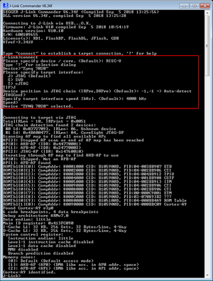
Please note that for the device selection in J-Link Commander, quotes are needed around the device name (as shown in the screenshot below). This is due to the nature of the Zynq7000 device names, containing spaces. Apart from that, there is nothing special to be taken care of.
Note: The device selection is mandatory to make sure that J-Link applies the correct connect and reset sequences to the Zynq 7000 series devices. By selecting "generic Cortex-A9" correct functionality cannot be guaranteed.
Board connection
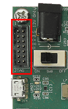
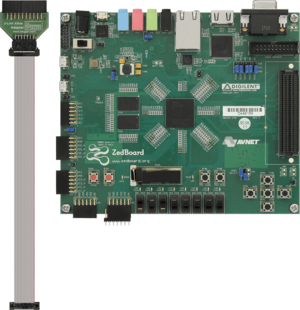
The ZedBoard provides a Xilinx specific 14-pin debug connector. In order to connect J-Link to this board, the J-Link Xilinx adapter is needed.


