Difference between revisions of "netX Studio"
(→Flasher Operations) |
(→Installing drivers for Segger J-Link) |
||
| Line 39: | Line 39: | ||
== Installing drivers for Segger J-Link == |
== Installing drivers for Segger J-Link == |
||
| + | |||
| + | {{Note|netX Studio do not distribute the SEGGER J-Link software, therefore it must be installed <br> |
||
| + | separately, then netX Studio CDT will automatically detect it (The location can be changed <br> |
||
| + | at any time via Edit > Preferences > SEGGER J-Link ).}} |
||
To install drivers for Segger J-Link, follow these steps: |
To install drivers for Segger J-Link, follow these steps: |
||
Revision as of 15:07, 3 April 2024
Contents
Installation of netX Studio CDT
The installation process for the netX Studio CDT software on a development PC is described in this section.
Requirements for Installing netX Studio CDT
Before proceeding with the installation, ensure that your system meets the following requirements:
- General Requirements:
- Operating system: Windows® 10 or Windows® 11.
- Internet access is required for downloading third-party development tools like the ARM GNU toolchain and OpenOCD.
- Specific Requirements (if applicable):
- Uninstall any previous versions of netX Studio from your development PC.
- Uninstall HiTOP USB drivers from your development PC before installing the netX Studio CDT software.
Hardware Requirements for Development PC:
- Processor: Dual-core 2 GHz (or equivalent).
- RAM: Minimum 2 GB, recommended 4 GB.
- Free disk space: Approximately 3 GB, SSD recommended.
- Graphic resolution: 1024 x 768 pixels.
Running the netX Studio CDT Setup Program
To install netX Studio CDT on your development PC:
1. Double-click the `netX Studio CDT Vx.xxxx.x.xxxx x86 Setup.msi` file. 2. Follow the instructions provided by the netX Studio CDT Setup Wizard:
  * Accept the license agreement.
  * Choose the installation destination folder.
  * Select additional tasks according to preferences.
  * Begin the installation process.
  * Grant necessary permissions if prompted by the User Account Control.
3. Upon successful installation, click "Finish" to complete the setup wizard.
After installing netX Studio CDT, it's essential to complete the installation of required development tools, which will be automatically initiated on launching netX Studio CDT for the first time.
This completes the installation process of netX Studio CDT on your PC, enabling you to proceed with your development tasks efficiently.
Installing drivers for Segger J-Link
netX Studio do not distribute the SEGGER J-Link software, therefore it must be installed
separately, then netX Studio CDT will automatically detect it (The location can be changed
To install drivers for Segger J-Link, follow these steps:
- Open the SEGGER website: [1](https://www.segger.com/downloads/jlink/#J-LinkSoftwareAndDocumentationPack)
- Select version 7.96 or later.
- Run the setup with administrator privileges.
- Select "Install USB driver for J-Link."
- Click "Next."
After installing the SEGGER J-Link software, netX Studio CDT automatically adds "SEGGER J-Link" to the preferences page.
- Open "Edit > Preferences" to view the result.
Creating a New Project
netX Studio CDT comes with built-in project templates that contain the bare minimum resources required for a running application. These templates can serve as a starting point for a new project.
To create a new netX CDT project:
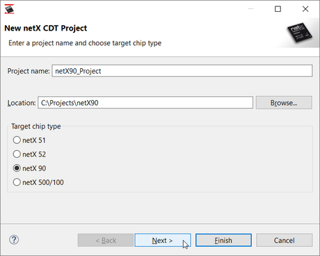
- Select File > New > netX CDT Project from the main menu.
- Enter a project name and select the target chip type.
- Optionally, change the project location.
- Click "Finish."
- The project is created and displayed in the Project Explorer.
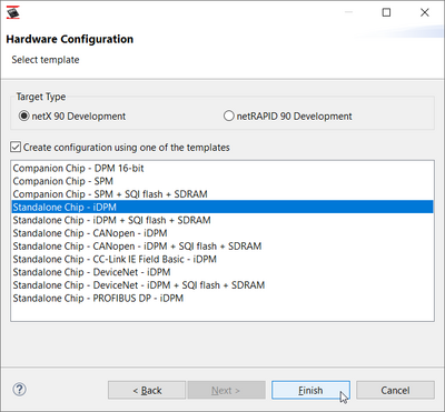
- The new project wizard for netX 90 offers additional options for configuration.
- Click Next to proceed with the netX 90-specific options of the wizard.
J-Link Debug Settings
Before you start debugging, you can adjust the target debug settings.
Select Debug > Debug Settings from the main menu. By default, netX Studio CDT uses OpenOCD for debugging. As an alternative, netX Studio CDT can use J-Link for debugging.
These settings influence the way J-Link is started, how it connects to, and initializes the target device.
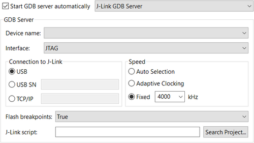
Start J-Link GDB Server Automatically
If "Start GDB server automatically" is checked and the option "J-Link GDB Server" is selected, netX Studio CDT will automatically start the J-Link connecting to the specified hardware debugger.
Device Name
The device name offers a drop-down list for the netX chip type. For netX 90, select "netX90_APP".
Interface
The interface drop-down list allows you to select JTAG or SWD.
Connection to J-Link
To connect to the J-Link adapter, you can use USB, USB with serial number, or TCP/IP (with IP address).
Flash Breakpoints
Disables (false) or enables (true) breakpoints to be used in the Flash memory.
Config Script (Advanced)
You can use the field "Config script" to optionally specify a customized, project-specific configuration script for J-Link.
Mode Setting
The option "Mode" determines how netX Studio CDT will connect to the target device:
- Run: The target will be reset, initialized, and halted at the first instruction.
- Attach: The target will be halted at the current instruction.
Use the mode "Run" to start debugging an application from the first instruction that is executed after a reset.
Use the mode "Attach" to attach to a running application on the netX, e.g., attach and debug your application once it has been flashed to the device.
Using J-Link Commander as Flashing tool
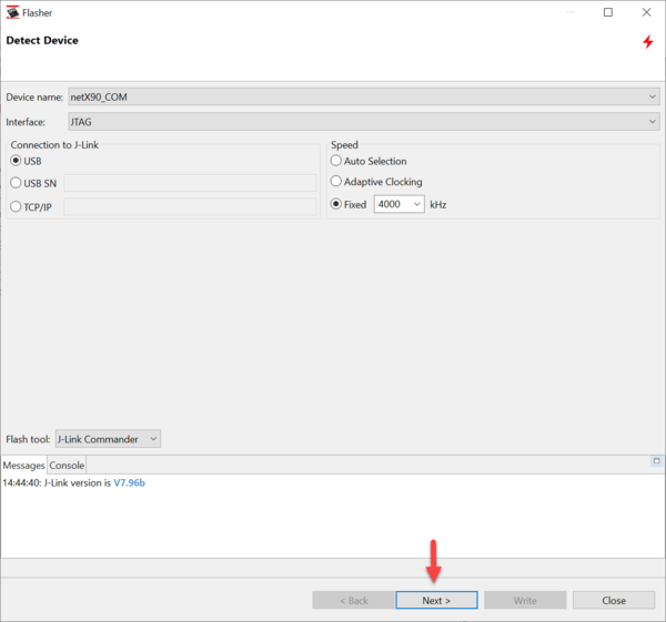
To start the tool, select Tools > Flasher from the main menu, or click the Flasher button on the toolbar and select JLink Commander under Flash tool.
Device Selection
When using J-Link Commander for flashing operations, you have the option to set:
- The interface to JTAG or SWD,
- The connection to the J-Link probe,
- The speed of the operation.
Flasher Operations
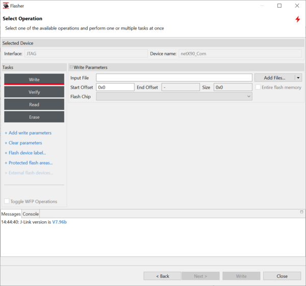
On the second page of the Flasher wizard, you can select one of the available Flasher operations with J-Link Commander:
The tool allows you to perform one or more tasks.
To perform tasks with J-Link Commander:
- Select one of the supported operations on the left: Click the button "Write/Verify/Read/Erase" to switch between the operations (the active operation is underlined in red).
