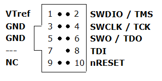
9-pin JTAG/SWD connector
This article describes the J-Link 9-pin JTAG/SWD connector, available on J-Link Edu Mini.
Pinout
Some target boards only provide a 9-pin JTAG/SWD connector for Cortex-M.
For these devices SEGGER provides a 20-pin -> 9-pin Cortex-M adapter.
The J-Link EDU mini also comes with a 9-pin Cortex-M connector.
| PIN | SIGNAL | TYPE | Description |
|---|---|---|---|
| 1 | VTref | Input | This is the target reference voltage. It is used to check if the target has power, to create the logic-level reference for the input comparators and to control the output logic levels to the target. It is normally fed from VDD of the target board and must not have a series resistor. |
| 2 | SWDIO / TMS | I/O / Output |
|
| 4 | SWCLK / TCK | Output |
|
| 6 | SWO / TDO | Input |
|
| --- | --- | --- | This pin (normally pin 7) is not existent on the 9-pin JTAG/SWD connector. |
| 8 | NC / TDI | NC / Output |
|
| 9 | NC(TRST) | NC | By default, TRST is not connected, but the Cortex-M Adapter comes with a solder bridge (NR1) which allows TRST to be connected to pin 9 of the Cortex-M adapter. |
| 10 | nRESET | I/O | Target CPU reset signal. Typically connected to the RESET pin of the target CPU, which is typically called "nRST", "nRESET" or "RESET". This signal is an active low signal. |
| 3, 5 | GND | Ground | GND pins connected to GND in J-Link. They should also be connected to GND in the target system. |
