Flasher/How to use WireCheck
Contents
WireCheck utility
Intended use of WireCheck
WireCheck is a tool intended to help the user find fatal wiring errors from the flasher to his device.
- WireCheck can detect if output pins are stuck to LOW or stuck to HIGH.
- WireCheck can detect if an output pin is interconnected to another pin which is in use.
- WireCheck can detect whether an input pin is at the specified level.
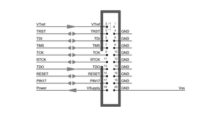
The flasher has 8 inputs/outputs, i.e. the odd pins from pin 3 to pin 17. Pin 13 is for input only. The other pins can be configured bidirectionally. VTref (pin 1) and V5-Supply (pin 19) have different functions.
Pins on the Flashers 20 pin header
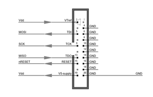
Whenever you want to program a new device, you have to connect it to the Flasher according to the device's corresponding wiring diagram.
Example wiring diagram
You can make a number of mistakes with the wiring. Many of these can be found with the WireCheck tool. However, the tool requires the cooperation of the operator.
WireCheck Tool is part of the UniversalFlasher
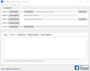
Start “UniversalFlasher.exe”
Select Device
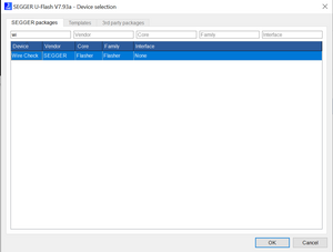
Step #1: Select device: find the device by typing “wi…” into the Device selection field. Then double ckick on it.
Select DataFile
Step #2: You can skip this point as a data file is not required by the WireCheck tool.
Select Flasher
Step #3: Select the flasher on which you want to perform the WireCheck.
Pin settings
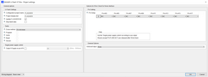
Step #4: Click on "Configure project" to open the "Project settings". In the "Pin Setting" area of the "Project settings", the tool must now be told how the Flasher pins are to be used.
For all output pins it is enough to choose OUTPUT for the used pins. Output pins can be easily determined in the wiring of the device. Input pins can also be easily determined in the wiring of the device. However, you have to check the data sheet of the device or measure the pin to see whether the pin is HIGH or LOW in the idle state. Unused pins are marked with NC.
Here an example for the ATMega connected via the ISP interface shown in the example wiring diagram above:
Power supply
Now you have to take care about your devices power supply. You have 2 options:
- The target has its own power supply: Keep the “Output VSupply on pin #19” unchecked
- The Flasher power the Target: Please check “Output VSupply on pin #19”.
Save project and send to Flasher
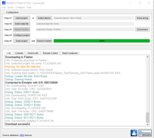
Step #5: Save your project and send your configuration to the Flasher:
You can ignore the Warning: "No data file selected" as it is not required for WireCheck!
Start WireCheck
Please select the Console TAB and type #AUTO or #START
The test is executed very fast. If all test sequences PASS the test ends with an Ok message.
In case of errors you will see an output like this:
#start
#ACK
#STATUS:INITIALIZING
#STATUS:CONNECTING
#INFO:WIRECHK.PEX Nov 30 2023 15:41:24
#INFO:Verbosity: 00000000
#INFO:ERR: Reset not HIGH
#INFO:ERR Crossconnect: 00000009
#INFO:ERR Crossconnect: 00000005
#INFO:ERR Crossconnect
#INFO:ERR Pin NOT HIGH: 00000013
#INFO:ERRORs occured!
#ERR255:Error while flashing
For more information you can increase the Verbose Output in the General Options!
#ACK
#STATUS:INITIALIZING
#STATUS:CONNECTING
#INFO:WIRECHK.PEX Nov 30 2023 15:41:24
#INFO:Verbosity: 00000002
#INFO:**************************
#INFO:*** WireCheck starting ***
#INFO:--- Showing Pin Config ---
#INFO:Pin Config: 00000003
#INFO:Value: 00000000
#INFO:Pin Config: 00000005
#INFO:Value: 00000001
#INFO:Pin Config: 00000007
#INFO:Value: 00000000
#INFO:Pin Config: 00000009
#INFO:Value: 00000001
#INFO:Pin Config: 00000011
#INFO:Value: 00000000
#INFO:Pin Config: 00000013
#INFO:Value: 00000003
#INFO:Pin Config: 00000015
#INFO:Value: 00000001
#INFO:Pin Config: 00000017
#INFO:Value: 00000000
#INFO:--- Checking Outputs ---
#INFO:Output Pin: 00000005
#INFO: Ok
#INFO:Output Pin: 00000009
#INFO: Ok
#INFO:Output Pin: 00000015
#INFO:ERR: Reset not HIGH
#INFO:--- Checking Crossconnections ---
#INFO:--- Reading all Pin levels ---
#INFO:Pin State: 00000003
#INFO: LOW
#INFO:Pin State: 00000005
#INFO: LOW
#INFO:Pin State: 00000007
#INFO: LOW
#INFO:Pin State: 00000009
#INFO: LOW
#INFO:Pin State: 00000011
#INFO: LOW
#INFO:Pin State: 00000013
#INFO: LOW
#INFO:Pin State: 00000015
#INFO: LOW
#INFO:Pin State: 00000017
#INFO: LOW
#INFO:Check on Pin: 00000005
#INFO:ERR Crossconnect: 00000009
#INFO:To Pin # Ok 00000013
#INFO:To Pin # Ok 00000015
#INFO:Check on Pin: 00000009
#INFO:ERR Crossconnect: 00000005
#INFO:To Pin # Ok 00000013
#INFO:To Pin # Ok 00000015
#INFO:Check on Pin: 00000013
#INFO:To Pin # Ok 00000005
#INFO:To Pin # Ok 00000009
#INFO:To Pin # Ok 00000015
#INFO:Check on Pin: 00000015
#INFO:To Pin # Ok 00000005
#INFO:To Pin # Ok 00000009
#INFO:To Pin # Ok 00000013
#INFO:ERR Crossconnect
#INFO:--- Checking Inputs ---
#INFO:Input Pin: 00000013
#INFO: LOW
#INFO:ERR Pin NOT HIGH: 00000013
#INFO:**************************
#INFO:*** WireCheck finished ***
#INFO:--- Relasing all pins ---
#INFO:ERRORs occured!
#ERR255:Error while flashing
What tests does WireCheck carry out?
After reading the user's configuration, WireCheck performs the following tests:
- Output Check: It is checked whether the configured Flasher outputs can switch LOW and HIGH correctly.
- Crossconnect Check: It is checked whether an output has an unwanted connection to another configured pin.
- Input Check: It is checked whether an input is at the configured level.
Limitations of WireCheck
- The High Frequency (Crosstalk) behavior and the quality of the ground wiring cannot be tested.
- Swapped input and output pins cannot be detected.
- Wiring to the wrong device pins cannot be recognized.
Next steps
If the WireCheck was successful, the next test should be to "talk" to the device. To do this, WireCheck must be terminated. Then set up a project with the corresponding device you are using. Download your configuration to your Flasher and type #START in the Console tab window.
Depending on the device and "Verbose Output" you will see some device specific information.
< #START
> #ACK
> #STATUS:INITIALIZING
> #STATUS:CONNECTING
> #INFO:20230921 MEGA_ISP.PEX
> #INFO:Verbosity: info
> #INFO:Device Identification OK:
> #INFO:Manufacturer read:      0000001E
> #INFO:MemSizeID read:         00000097
> #INFO:Part Number read:       00000006
> #INFO:Fuse Byte Low:          000000E2
> #INFO:Fuse Byte High:         00000099
> #INFO:Fuse Bits Extended:     000000FF
> #INFO:Read Calib  Byte:       00000000
> #INFO:Calibration Byte:       0000008B
> #INFO:EEPROM destination Addr:00000000
> #INFO:High speed programming possible
> #INFO:*********************************
> #INFO:--- No config words written   ---
> #INFO:--- No lock bits written      ---
> #INFO:--- Keep application in reset ---
> #OK (Total 0.177s)
If #START is finished with #OK your wiring to the device is successfully completed.
