LPCXpresso LPC1769
Connecting J-Link to LPCXpresso LPC1769
For connecting J-Link with the LPC1769 the debug interface signal lines between the on-board debugger (LPC-Link) and the MCU must be separated, so that the LPC-Link cannot change pin states while the J-Link communicates with the target.
Some bridge wires in the middle of the board (J4) must be cut (for example by scratching):
1  <--> 2  ( 3V3              ==> don't change)
3  <--> 4  ( JTAG_TMS_SWDIO   ==> cut )
5  <--> 6  ( JTAG_TCLK_SWCLK  ==> cut)
7  <--> 38 ( JTAG_TDO_SWO     ==> cut )
9  <--> 10 ( JTAG_TDI         ==> cut )
11 <--> 12 ( JTAG_RESET       ==> cut )
13 <--> 14 ( EXT_POW          ==> don't change)
15 <--> 16 ( GDN              ==> don't change)
After isolating the on-board debugger from the target MCU a new connector needs to be soldered to route debug interface signals to the J-Link.
J4      J-Link
2  <--> 1  (VTref)
4  <--> 7  (TMS)
6  <--> 9  (TCK)
8  <--> 13 (TDO)
10 <--> 5  (TDI)
12 <--> 15 (RESET)
16 <--> 4  (GND)
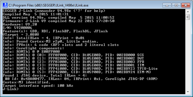
A successful connection should look like this:
