TI LP-MSPM0C1104
This article describes specifics for the TI LP-MSPM0C1104 evaluation board. It can be used to test & verify MSPM0C device support.
Minimum requirements
- J-Link software V7.94 or later
Preparing for J-Link
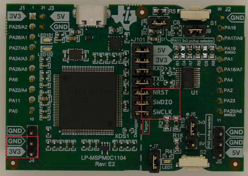
The TI LP-MSPM0C1104 board does not have a external debug interface connector, so the jumper pins can be used instead:
- Remove last three jumpers of J101 (NRST, SWDIO, SWCLK).
- Connect NRST, SWDIO, SWCLK wires from J-Link adapter to the right side(labeled as Target) of the J101 connector.
- Connect GND and VTREF wires to the J4 connector.
The following table describes the pinning and how it should be connected to the SEGGER Flying Wire Adapter.
| MSPM0C1104 Board | Flying wire adapter |
|---|---|
| J4 GND | GND |
| J4 3V3 | VTREF |
| J101 NRST(Right) | RESET |
| J101 SWDIO(Right) | SWDIO |
| J101 SWCLK(Right) | SWCLK |
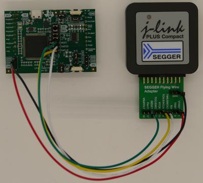
In this example we are using a J-Link Plus Compact. The resulting connection will then look like this:
- Power the board via the USB-Micro port
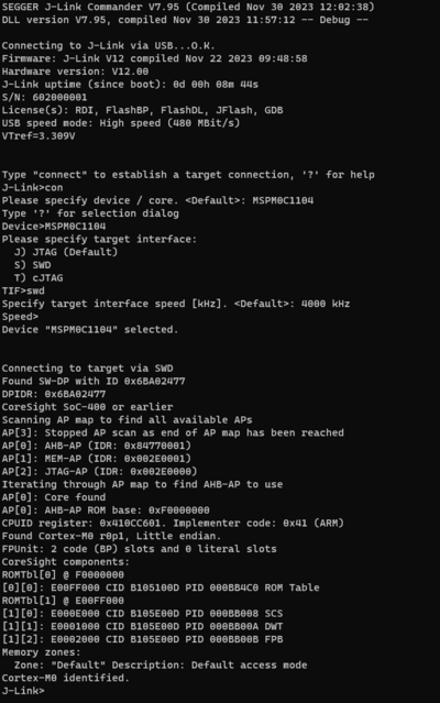
- Verify the Connection with e.g. J-Link Commander. The output should look as follows:
Example Project
The following example project was created with the SEGGER Embedded Studio project wizard and runs out-of-the-box on the TI LP-MSPM0C1104. It is a simple Hello World sample linked into the internal flash.
SETUP
- J-Link software: V7.94
- Embedded Studio: V7.32
- Hardware: TI LP-MSPM0C1104
- Link: File:TI MSPM0C1104 TestProject ES V732.zip


