Difference between revisions of "TI LP-MSPM0G3507"
(→Example Project) |
|||
| Line 14: | Line 14: | ||
== Example Project== |
== Example Project== |
||
| − | The following example project was created with the SEGGER Embedded Studio project wizard and runs out-of-the-box on the TI LP-MSPM0G3507. It is a simple Hello World sample linked into the internal flash. |
+ | The following example project was created with the SEGGER Embedded Studio project wizard and runs out-of-the-box on the TI LP-MSPM0G3507. It is a simple Hello World sample linked into the internal flash. |
| + | The folder also contains an Ozone project which can be used with the prerequisites below. |
||
====SETUP==== |
====SETUP==== |
||
*J-Link software: V7.68 |
*J-Link software: V7.68 |
||
*Embedded Studio: V6.30 |
*Embedded Studio: V6.30 |
||
| + | *Ozone: V3.30a |
||
*Hardware: TI LP-MSPM0G3507 |
*Hardware: TI LP-MSPM0G3507 |
||
*Link: [[File:TI_MSPM0G3507_TestProject_ES_V630.zip]] |
*Link: [[File:TI_MSPM0G3507_TestProject_ES_V630.zip]] |
||
Revision as of 10:43, 24 July 2023

This article describes specifics for the TI LP-MSPM0G3507 evaluation board. It can be used to test & verify MSPM0G device support.
Minimum requirements
- J-Link software V7.68 or later
Preparing for J-Link
- Remove all but the first three left jumpers of J101
- Connect the J-Link to the SWD header (J103)
- Power the board via the USB jack of the break out board.
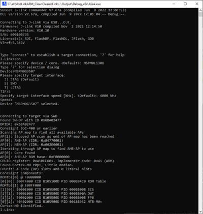
- Verify the Connection with e.g. J-Link Commander. The output should look as follows:

Example Project
The following example project was created with the SEGGER Embedded Studio project wizard and runs out-of-the-box on the TI LP-MSPM0G3507. It is a simple Hello World sample linked into the internal flash. The folder also contains an Ozone project which can be used with the prerequisites below.
SETUP
- J-Link software: V7.68
- Embedded Studio: V6.30
- Ozone: V3.30a
- Hardware: TI LP-MSPM0G3507
- Link: File:TI MSPM0G3507 TestProject ES V630.zip