Difference between revisions of "HPMicro HPM6750EVKMINI"
(→Preparing for J-Link) |
|||
| Line 14: | Line 14: | ||
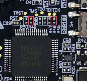
# Disconnect TCK and TRST to FT2232 by removing R45 and R49 <br>[[File:HPM6750EVKMINI_R45_R49.png|300px]] |
# Disconnect TCK and TRST to FT2232 by removing R45 and R49 <br>[[File:HPM6750EVKMINI_R45_R49.png|300px]] |
||
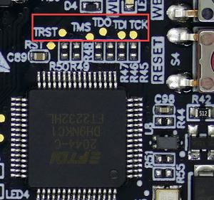
# Connect TDO (T7), TDI (T8), TCK (T9), TMS (T10), and TRST (T11) to external debug probe. <br>[[File:HPM6750EVKMINI_TDO_TDI_TCK_TMS_TRST.png|300px]] |
# Connect TDO (T7), TDI (T8), TCK (T9), TMS (T10), and TRST (T11) to external debug probe. <br>[[File:HPM6750EVKMINI_TDO_TDI_TCK_TMS_TRST.png|300px]] |
||
| − | # |
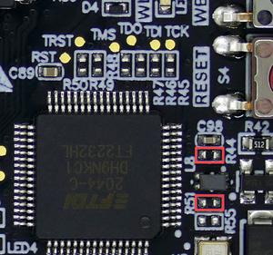
+ | # VTRef and GND can be connected from R44(VTRef) and R51(GND) respectively on the side facing the USB-C port. <br>[[File:HPM6750EVKMINI_VREF_GND.png|300px]] |
After that, connect the board with the soldered on wires to your J-Link (see table below)<br>For information about the J-Link pinout please refer to the following page: [https://www.segger.com/products/debug-probes/j-link/technology/interface-description/#jtag-interface-connection-20-pin J-Link JTAG pinout]. |
After that, connect the board with the soldered on wires to your J-Link (see table below)<br>For information about the J-Link pinout please refer to the following page: [https://www.segger.com/products/debug-probes/j-link/technology/interface-description/#jtag-interface-connection-20-pin J-Link JTAG pinout]. |
||
Revision as of 11:17, 11 March 2022
This article describes specifics for the HPMicro HPM6750EVKMINI evaluation board.

Minimum requirements
- J-Link software V7.63c or later
Preparing for J-Link
To use HPM6750EVKMINI with an external J-Link some soldering is neccessary.
- Disconnect TCK and TRST to FT2232 by removing R45 and R49
- Connect TDO (T7), TDI (T8), TCK (T9), TMS (T10), and TRST (T11) to external debug probe.
- VTRef and GND can be connected from R44(VTRef) and R51(GND) respectively on the side facing the USB-C port.


After that, connect the board with the soldered on wires to your J-Link (see table below)
For information about the J-Link pinout please refer to the following page: J-Link JTAG pinout.
The result should be looking like this:

- Power the board via the USB port (J3).
- Verify the Connection with e.g. J-Link Commander. The output should look as follows:
