Difference between revisions of "TI LP-MSPM0L2228"
(Created page with "450px|thumb|right|TI LP-MSPM0L2228 evaluation board This article describes specifics for the TI LP-MSPM0L2228 evaluation board. It can be u...") |
|||
| Line 1: | Line 1: | ||
| + | [[Category:Evalboards]] |
||
[[File:TI_LP-MSPM0L2228_board.jpg|450px|thumb|right|TI LP-MSPM0L2228 evaluation board]] |
[[File:TI_LP-MSPM0L2228_board.jpg|450px|thumb|right|TI LP-MSPM0L2228 evaluation board]] |
||
This article describes specifics for the TI LP-MSPM0L2228 evaluation board. |
This article describes specifics for the TI LP-MSPM0L2228 evaluation board. |
||
Latest revision as of 14:39, 15 May 2024

This article describes specifics for the TI LP-MSPM0L2228 evaluation board. It can be used to test & verify MSPM0Lx228 device support.
Minimum requirements
- J-Link software V7.96d or later
Preparing for J-Link
- Remove SWDIO and SWCLK jumpers of J14.
- Connect the J-Link to the SWD header (XDS110).
- Power the board via the USB jack of the break out board.
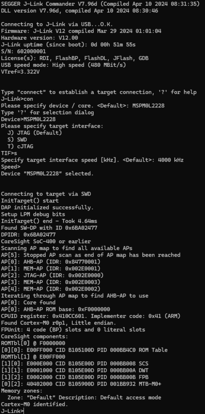
- Verify the Connection with e.g. J-Link Commander. The output should look as follows:

Example Project
The following example project was created with the SEGGER Embedded Studio project wizard and runs out-of-the-box on the TI LP-MSPM0L2228. It is a simple Hello World sample linked into the internal flash.
SETUP
- J-Link software: V7.96d
- Embedded Studio: V8.10
- Hardware: TI LP-MSPM0L2228
- Link: File:TI MSPM0L2228 TestProject ES 8V10.zip