J-Link Commander
J-Link Commander (JLink.exe / JLinkExe) is a free, command line based utility that can be used for verifying proper functionality of J-Link as well as for simple analysis of the target system with J-Link. It supports some simple commands, such as memory dump, halt, step, go etc. to verify the target connection. The J-Link Commander is part of the J-Link Software and Documentation Pack, which is available for download on the SEGGER webpage.
The sources of the J-Link Commander are available as part of the J-Link SDK.
Contents
- 1 Commands
- 1.1 ?
- 1.2 Exit
- 1.3 ExitOnError
- 1.4 Sleep
- 1.5 Log
- 1.6 ExpDevList
- 1.7 ExpDevListXML
- 1.8 USB
- 1.9 IP
- 1.10 SelectProbe
- 1.11 ShowEmuList
- 1.12 Power
- 1.13 VTREF
- 1.14 VCOM
- 1.15 ShowFWInfo
- 1.16 ShowHWStatus
- 1.17 License
- 1.18 IPAddr
- 1.19 GWAddr
- 1.20 DNSAddr
- 1.21 ShowConf
- 1.22 Calibrate
- 1.23 Connect
- 1.24 Device
- 1.25 SelectInterface
- 1.26 Speed
- 1.27 LE
- 1.28 BE
- 1.29 Halt
- 1.30 IsHalted
- 1.31 WaitHalt
- 1.32 Go
- 1.33 Reset
- 1.34 ResetX
- 1.35 RSetType
- 1.36 Step
- 1.37 IS
- 1.38 MS
- 1.39 Regs
- 1.40 RReg
- 1.41 WReg
- 1.42 MoE
- 1.43 SetBP
- 1.44 ClearBP
- 1.45 SetWP
- 1.46 ClearWP
- 1.47 VCatch
- 1.48 SetPC
- 1.49 ReadAP
- 1.50 WriteAP
- 1.51 ReadDP
- 1.52 WriteDP
- 1.53 RCP15Ex
- 1.54 WCP15Ex
- 1.55 Term
- 1.56 Mem
- 1.57 Mem8
- 1.58 Mem16
- 1.59 Mem32
- 1.60 Write1
- 1.61 Write2
- 1.62 Write4
- 1.63 JTAGConf
- 1.64 JTAGId
- 1.65 WJTAGIR
- 1.66 WJTAGDR
- 1.67 WJTAGRaw
- 1.68 ResetTAP
- 1.69 ResetTRST
- 1.70 ICE
- 1.71 ReadICE
- 1.72 WriteICE
- 1.73 TClear
- 1.74 TSetSize
- 1.75 TSetFormat
- 1.76 TShowRegions
- 1.77 TStart
- 1.78 TStop
- 1.79 SWOSpeed
- 1.80 SWOStart
- 1.81 SWOStop
- 1.82 SWOStat
- 1.83 SWORead
- 1.84 SWOShow
- 1.85 SWOFlush
- 1.86 SWOView
- 1.87 Erase
- 1.88 LoadFile
- 1.89 SaveBin
- 1.90 VerifyBin
- 1.91 FWrite
- 1.92 FRead
- 1.93 FShow
- 1.94 FDelete
- 1.95 FSize
- 1.96 FList
- 1.97 SecureArea
- 1.98 PowerTrace
- 1.99 TestWSpeed
- 1.100 TestRSpeed
- 1.101 TestCSpeed
- 1.102 TestNWSpeed
- 1.103 TestNRSpeed
- 1.104 MR
- 1.105 Clock
- 1.106 Clock00
- 1.107 ClrTCK
- 1.108 SetTCK
- 1.109 ClrTDI
- 1.110 SetTDI
- 1.111 ClrTMS
- 1.112 SetTMS
- 1.113 ClrTRST
- 1.114 SetTRST
- 1.115 ClrRESET
- 1.116 SetRESET
- 2 Using J-Link Command Files
- 3 Perform flash download
- 4 Batch processing
- 5 JLink.exe return value
- 6 Using J-Link Command Strings
- 7 Changing J-Link Reset Strategy
- 8 Connecting to a specific J-Link
- 9 Setup External CFI NOR Flash
- 10 Command specifics
Commands
The table below lists the available commands of J-Link Commander. Detailed descriptions of the commands can be found in the sections below. All commands are accepted case insensitive.
This list is only valid for the latest version of the J-Link Commander. In case of doubt, use the ? command.
| Command (long) | Command (short) | Explanation |
|---|---|---|
| Basic | ||
| ? | ? | Show information about all or specific commands |
| Exit | Exit | Close J-Link connection and quit |
| ExitOnError | EoE | Exit on error |
| Sleep | Sleep | Waits the given time (in milliseconds) |
| Log | Log | Enables log to file |
| ExpDevList | ExpDevList | Export device names from DLL internal device list to text file |
| ExpDevListXML | ExpDevListXML | Export device names from DLL internal device list to XML file |
| Configuration - J-Link | ||
| USB | USB | Connect to J-Link via USB |
| IP | IP | Connect to J-Link via TCP/IP or to Remote Server |
| SelectProbe | SelPrb | Show list of all connected probes via specified interface. The Probe to communicate with can then be selected |
| ShowEmuList | ShowEmuList | Show list of all connected probes via specified interface |
| Power | Power | Switch power supply for target (5V-Supply pin) on or off |
| VTREF | VTREF | Set fixed value for VTref on J-Link |
| VCOM | VCOM | Enable/disable VCOM Takes effect after power cycle of the Probe |
| ShowFWInfo | F | Show firmware info |
| ShowHWStatus | St | Show hardware status |
| License | License | Show list of all available license commands |
| IPAddr | IPAddr | Show/Assign IP address and subnetmask of/to connected Probe |
| GWAddr | GWAddr | Show/Assign network gateway address of/to connected Probe |
| DNSAddr | DNSAddr | Show/Assign network DNS server address of/to connected Probe |
| ShowConf | Conf | Show configuration of the connected Probe |
| Calibrate | Calib | Calibrate the target current measurement |
| Configuration - Target (CPU) | ||
| Connect | Con | Connect to target device |
| Device | Device | Select specific device J-Link shall connect to |
| SelectInterface | SI | Select target interface |
| Speed | Speed | Set target interface speed |
| LE | LE | Change mode to little endian |
| BE | BE | Change mode to big endian |
| Debugging | ||
| Halt | H | Halt CPU |
| IsHalted | IH | Return current CPU state |
| WaitHalt | WH | Wait until CPU is halted or timeout is reached |
| Go | G | Start CPU if halted |
| Reset | R | Reset CPU |
| ResetX | RX | Reset CPU with delay after reset |
| RSetType | Rst | Set the current reset type |
| Step | S | Execute step(s) on the CPU |
| IS | IS | Identify length of scan chain select register |
| MS | MS | Measure length of scan chain |
| Regs | Regs | Display CPU register contents |
| RReg | RReg | Read register |
| WReg | WReg | Write register |
| MoE | MoE | Shows mode-of-entry (CPU halt reason) |
| SetBP | SetBP | Set breakpoint |
| ClearBP | ClrBP | Clear breakpoint |
| SetWP | SetWP | Set watchpoint |
| ClearWP | ClrWP | Clear watchpoint |
| VCatch | VC | Write vector catch |
| SetPC | SetPC | Set the PC to specified value |
| ReadAP | ReadAP | Read CoreSight AP register |
| WriteAP | WriteAP | Write CoreSight AP register |
| ReadDP | ReadDP | Read CoreSight DP register |
| WriteDP | WriteDP | Write CoreSight DP register |
| RCP15Ex | RCE | Read CP15 register |
| WCP15Ex | WCE | Write CP15 register |
| Term | Term | Visualize printf output using DCC (SEGGER DCC handler running on target) |
| Debugging - Memory operation | ||
| Mem | Mem | Read memory and show corresponding ASCII values |
| Mem8 | Mem8 | Read 8-bit items |
| Mem16 | Mem16 | Read 16-bit items |
| Mem32 | Mem32 | Read 32-bit items |
| Write1 | W1 | Write 8-bit items |
| Write2 | W2 | Write 16-bit items |
| Write4 | W4 | Write 32-bit items |
| Debugging - JTAG related | ||
| JTAGConf | JTAGConf | Set number of IR/DR bits before Target device |
| JTAGId | I | Read JTAG Id |
| WJTAGIR | WJIR | Write JTAG command (IR) |
| WJTAGDR | WJDR | Write JTAG data (DR) |
| WJTAGRaw | WJR | Write Raw JTAG data |
| ResetTAP | RTAP | Reset TAP Controller using state machine (111110) |
| ResetTRST | RT | Reset TAP Controller using nTRST |
| Debugging - ICE | ||
| ICE | ICE | Show state of the embedded ICE macrocell (ICE breaker) |
| ReadICE | RI | Read Ice register |
| WriteICE | WI | Write Ice register |
| TRACE | ||
| TClear | TC | Clear TRACE buffer |
| TSetSize | TSS | Set TRACE size of trace buffer |
| TSetFormat | TSF | Set TRACE Format |
| TShowRegions | TSR | Show TRACE Regions (and analyze trace buffer) |
| TStart | TStart | Start TRACE |
| TStop | TStop | Stop TRACE |
| SWO | ||
| SWOSpeed | SWOSpeed | Show supported SWO speeds |
| SWOStart | SWOStart | Start SWO |
| SWOStop | SWOStop | Stop SWO |
| SWOStat | SWOStat | Display SWO status |
| SWORead | SWORead | Read and display SWO data |
| SWOShow | SWOShow | Read and analyze SWO data |
| SWOFlush | SWOFlush | Flush SWO data |
| SWOView | SWOView | View SWO terminal data |
| Flash programming | ||
| Erase | Erase | Erase flash (range) of selected device |
| LoadFile | LoadFile | Load data file into target memory |
| SaveBin | SaveBin | Save target memory range into binary file |
| VerifyBin | VerifyBin | Verfy if specified bin file is at the specified target memory location |
| Flasher File I/O Commands | ||
| FWrite | FWr | (Flasher only) Write file to probe |
| FRead | FRd | (Flasher only) Read file from probe |
| FShow | FShow | (Flasher only) Read and display file from probe |
| FDelete | FDel | (Flasher only) Delete file on probe |
| FSize | FSz | (Flasher only) Display size of file on probe |
| FList | FList | (Flasher only) List directory on probe |
| SecureArea | SecureArea | (Flasher only) Creates/Removes secure area on probe |
| Measurement and test commands | ||
| PowerTrace | PowerTrace | Perform power trace (not supported by all models) |
| TestWSpeed | TestW | Measure download speed into target memory |
| TestRSpeed | TestR | Measure upload speed from target memory |
| TestCSpeed | TestC | Measure CPU speed |
| TestNWSpeed | TestNW | Measure network download speed |
| TestNRSpeed | TestNR | Measure network upload speed |
| MR | MR | Measure RTCK react time |
| J-Link Pin control | ||
| Clock | C | Output clock(s) on the TCK pin |
| Clock00 | C00 | Output clock(s) on the TCK pin, with TDI == 0 and TMS == 0 |
| ClrTCK | TCK0 | Clear TCK pin |
| SetTCK | TCK1 | Set TCK pin |
| ClrTDI | TDI0 | Clear TDI pin |
| SetTDI | TDI1 | Set TDI pin |
| ClrTMS | TMS0 | Clear TMS pin |
| SetTMS | TMS1 | Set TMS pin |
| ClrTRST | TRST0 | Clear TRST pin |
| SetTRST | TRST1 | Set TRST pin |
| ClrRESET | R0 | Clear RESET pin |
| SetRESET | R1 | Set RESET pin |
?
Show information about all commands or one specific command.
Syntax
? [<Command>]
| Parameter | Meaning |
|---|---|
| <Command> | (optional) Command, specific information is required for. |
Example
? Connect
Exit
Close target device connection, J-Link connection and closes the application.
Syntax
Exit
ExitOnError
Toggle exit J-Link Commander on error.
Short command
EoE
Syntax
EoE <1/0>
| Parameter | Meaning |
|---|---|
| 0 | Exit on error is off. |
| 1 | Exit on error is on. |
Sleep
Waits the given time. Usually used for J-Link Command Scripts.
Syntax
Sleep <Delay>
| Parameter | Meaning |
|---|---|
| Delay | Amount of time to sleep in ms. |
Example
Sleep 100
Log
Enables log to file.
Syntax
Log <filename>
| Parameter | Meaning |
|---|---|
| Filename | Log filename |
Example
Log "C:\Users\User\Desktop\MyLogFile.log"
ExpDevList
Export device names from DLL internal device list to text file.
Syntax
ExpDevList <Filename>
| Parameter | Meaning |
|---|---|
| Filename | Path to text file destination. |
Example
ExpDevList "C:\Users\User\Desktop\JLinkSuppDev.txt"
ExpDevListXML
Export device names from DLL internal device list to XML file.
Syntax
ExpDevListXML <Filename>
| Parameter | Meaning |
|---|---|
| Filename | Path to XML file destination. |
Example
ExpDevListXML "C:\Users\User\Desktop\JLinkSuppDev.xml"
USB
Connect to J-Link via USB. Opens the USB selection dialog if no port or SN is passed.
Syntax
USB [<SN>]
| Parameter | Meaning |
|---|---|
| SN | (optional) Serial number of the J-Link to connect to. |
Example
USB 600100000
IP
Connect to J-Link via TCP/IP or to Remote Server. Opens the IP selection dialog if no parameter is passed.
Syntax
IP [<IPAddr|RemoteServerString>]
| Parameter | Meaning |
|---|---|
| IPAddr | (optional) IP Address of the J-Link to connect to. |
| RemoteServerString | (optional) Remote server string of the J-Link remote server session to connect to. |
Example
IP tunnel:SomeTestName::jlink-europe.segger.com
SelectProbe
Show list of all connected probes via specified interface. The Probe to communicate with can then be selected.
Short command
SelPrb
Syntax
SelectProbe [<Interface0> <Interface1> ...]
| Parameter | Meaning |
|---|---|
| Interface | (optional) Interface, J-Links are supposed to be located at (USB, IP). |
Example
SelectProbe USB IP
ShowEmuList
Show list of all connected probes via specified interface (e.g. USB/IP)
Syntax
ShowEmuList [<Interface0> <Interface1> ...]
| Parameter | Meaning |
|---|---|
| Interface | (optional) Interface, J-Links are supposed to be located at (USB, IP). |
Example
ShowEmuList USB IP
Power
Switch power supply for target (J-Link pin 19, 5V-Supply) on or off, permanently or until next power-cycle.
Syntax
Power <State> [perm]
| Parameter | Meaning |
|---|---|
| State | On: Power supply on. Off: Power supply off. |
| perm | Sets the specified State value as default. |
Example
Power on
VTREF
Set fixed value for VTref on J-Link (0 == Auto detection).
Syntax
VTREF <Value[mV]>
| Parameter | Meaning |
|---|---|
| Value[mV] | Value, VTref is supposed to be set to in millivolt. |
Example
VTREF 3300
VCOM
Enable/disable VCOM. Takes effect after power cycle of the Probe.
Syntax
VCOM <enable|disable>
Example
VCOM enable
ShowFWInfo
Show firmware info.
Short command
F
ShowHWStatus
Show hardware status.
Short command
St
License
Execute license command. if no command is passed: Show a list of all available license commands.
Syntax
License [Command]
| Parameter Command | Meaning |
|---|---|
| add | Store a custom license on J-Link. Syntax: LicAdd <LicName> |
| erase | Erase all custom licenses on J-Link. |
| show | Show all licenses stored on J-Link. |
IPAddr
Show/Assign IP address and subnetmask of/to connected Probe.
Syntax
IPAddr
GWAddr
Show/Assign network gateway address of/to connected Probe.
Syntax
GWAddr
DNSAddr
Show/Assign network DNS server address of/to connected Probe.
Syntax
DNSAddr
ShowConf
Show configuration of the connected Probe.
Short command
Conf
Calibrate
Calibrate the target current measurement.
Short command
Calib
Connect
Connect to target device. If no device was preselected, the user is asked to provide the missing information about the connected device.
Short command
Con
Device
Select specific device J-Link shall connect to. If ? is passed: Show device selection dialog.
Syntax
Device <DeviceName>
| Parameter | Meaning |
|---|---|
| DeviceName | Valid device name: Device is selected. ?: Shows device selection dialog. |
Example
Device STM32F407VE
SelectInterface
Select target interface.
Short command
SI
Syntax
SelectInterface <Interface>
| Parameter | Meaning |
|---|---|
| Interface | Any supported target interface (e.g SWD, JTAG, ICSP, FINE, ...) |
Example
SelectInterface SWD
Speed
Set target interface speed.
Syntax
Speed <Setting>
| Parameter | Meaning |
|---|---|
| Setting | Decimal value: Interface speed in kHz. auto: Interface speed is selected automatically. adaptive: Interface speed is set to adaptive. |
Example
Speed 4000
LE
Change mode to little endian.
BE
Change mode to big endian.
Halt
Halt CPU.
Short command
H
IsHalted
Return current CPU state.
Short command
IH
WaitHalt
Wait until CPU is halted or timeout is reached. If no timeout (in ms) is provided, a default timeout of 1000 ms is used.
Short command
WH
Syntax
WaitHalt [<TimeoutMs>]
| Parameter | Meaning |
|---|---|
| TimeoutMs | (optional) Timeout in milliseconds. |
Example
WaitHalt 100
Go
Start CPU if halted.
Short command
G
Reset
Reset CPU.
Short command
R
ResetX
Reset CPU with delay after reset. This function is useful for some target devices which already contain an application or a boot loader and therefore need some time before the core is stopped, for example to initialize hardware, the memory management unit (MMU) or the external bus interface.
Short command
RX
Syntax
ResetX <DelayAfterReset>
| Parameter | Meaning |
|---|---|
| DelayAfterReset | Delay in ms. |
Example
RX 1000
RSetType
Set the current reset type.
Short command
Rst
Syntax
RSetType [<Type>]
| Parameter | Meaning |
|---|---|
| Type | Desired reset type. If no type is provided, a list of all available types is printed. |
Example
RSetType 0
Step
Execute step(s) on the CPU and show the executed instructions. If no number of steps is provided, one step is executed.
Short command
S
Syntax
Step [<NumSteps> (decimal)]
Example
Step 10
IS
Identify length of scan chain select register.
MS
Measure length of scan chain.
Syntax
MS <ScanChain>
| Parameter | Meaning |
|---|---|
| ScanChain | Scan chain to be measured. |
Regs
Display CPU register contents.
RReg
Read register. If no register name is passed, all available register names are printed.
Syntax
RReg <RegName>
| Parameter | Meaning |
|---|---|
| RegIndex | Register to read. |
Example
RReg R15 (PC)
WReg
Write register.
Short command
WReg
Syntax
WReg <RegName>, <Value>
| Parameter | Meaning |
|---|---|
| RegName | Register to write to. |
| Data | Data to write to the specified register. |
Example
WReg R15 (PC), 0x20000000
MoE
Shows mode-of-entry (Reason why CPU is halted).
SetBP
Set breakpoint.
Syntax
SetBP <addr> [<A/T>/<W/H>] [S/H]
| Parameter | Meaning |
|---|---|
| Addr | Address to be breakpointed. |
| A/T | Only for ARM7/9/11 and Cortex-R4 devices: A: ARM mode T: THUMB mode |
| W/H | Only for MIPS devices: W: MIPS32 mode (Word) H: MIPS16 mode (Half-word) |
| S/H | S: Force software BP H: Force hardware BP |
ClearBP
Clear breakpoint.
Short command
ClrBP
Syntax
ClearBP <BP_Handle>
SetWP
Set Watchpoint.
Syntax
SetWP <Addr(hex)> [<AccessType>] [<Size>] [<Data(hex)> [<DataMask(hex)> [<AddrMask(hex)>]]]
| Parameter | Meaning |
|---|---|
| Addr | Address to be breakpointed. |
| AccessType | Trigger on:
|
| Size |
|
| DataMask | Ignore data bits set to 1. |
| AddrMask | Ignore address bits set to 1. |
Example
// Stop if value 0x1000 is written to address 0x20000000 (32-bit access):
SetWP 0x20000000 W S32 0x1000 0 0
ClearWP
Clear watchpoint.
Short command
ClrWP
Syntax
ClearWP <WP_Handle>
VCatch
Write vector catch.
Short command
VC
Syntax
VCatch <Value>
SetPC
Set the PC to specified value.
Syntax
SetPC <Addr>
| Parameter | Meaning |
|---|---|
| Addr | Address the PC should be set to. |
ReadAP
Reads from a CoreSight AP register. This command performs a full-qualified read which means that it tries to read until the read has been accepted or too many WAIT responses have been received. In case actual read data is returned on the next read request (this is the case for example with interface JTAG) this command performs the additional dummy read request automatically.
Syntax
ReadAP <RegIndex>
| Parameter | Meaning |
|---|---|
| RegIndex | Index of AP register to read |
Example
//
// Read AP[0], IDR (register 3, bank 15)
//
WriteDP 2, 0x000000F0 // Select AP[0] bank 15
ReadAP 3              // Read AP[0] IDR
WriteAP
Writes to a CoreSight AP register. This command performs a full-qualified write which means that it tries to write until the write has been accepted or too many WAIT responses have been received.
Syntax
WriteAP <RegIndex>
| Parameter | Meaning |
|---|---|
| RegIndex | Index of AP register to write |
| Data32Hex | Data to write |
ReadDP
Reads from a CoreSight DP register. This command performs a full-qualified read which means that it tries to read until the read has been accepted or too many WAIT responses have been received. In case actual read data is returned on the next read request (this is the case for example with interface JTAG, not with SWD) this command performs the additional dummy read request automatically.
Syntax
ReadDP <RegIndex>
| Parameter | Meaning |
|---|---|
| RegIndex | Index of DP register to read |
WriteDP
Writes to a CoreSight DP register. This command performs a full-qualified write which means that it tries to write until the write has been accepted or too many WAIT responses have been received.
Syntax
WriteDP <RegIndex>
| Parameter | Meaning |
|---|---|
| RegIndex | Index of DP register to write |
| Data32Hex | Data to write |
Example
//
// Write DP SELECT register: Select AP 0 bank 15
//
WriteDP 2, 0x000000F0
RCP15Ex
Read CP15 register.
Short command
RCE
Syntax
RCE15Ex <Op1>, <CRn>, <CRm>, <Op2>
WCP15Ex
Write CP15 register.
Short command
WCE
Syntax
WCE15Ex <Op1>, <CRn>, <CRm>, <Op2>,
Term
Visualize printf output using DCC (SEGGER DCC handler running on target).
Mem
Read memory from the target system and show corresponding ASCII values. If necessary, the target CPU is halted in order to read memory. Zone names will be displayed on first connect to target with J-Link commander if available.
Syntax
Mem[<Zone>:]<Addr>, <NumBytes> (hex)
Example
Mem 0x0, 0x100
or
mem AHB-AP (AP1):0x20000000, 0x100
Mem8
Read memory from the target system in units of 8-bit. If necessary, the target CPU is halted in order to read memory.
Syntax
mem [<Zone>:]<Addr>, <NumBytes> (hex)
| Parameter | Meaning |
|---|---|
| Zone | Name of memory zone to access. |
| Addr | Start address. |
| Numbytes | Number of bytes to read. Maximum is 0x100000. |
Example
Mem8 0x0, 100
Mem16
Read memory from the target system in units of 16-bits. If necessary, the target CPU is halted in order to read memory.
Syntax
Mem16 [<Zone>:]<Addr>, <NumItems> (hex)
| Parameter | Meaning |
|---|---|
| Zone | Name of memory zone to access. |
| Addr | Start address. |
| Numbytes | Number of bytes to read. Maximum is 0x100000. |
Example
Mem16 0x0, 100
Mem32
Read memory from the target system in units of 32-bits. If necessary, the target CPU is halted in order to read memory.
Syntax
Mem32 [<Zone>:]<Addr>, <NumItems> (hex)
| Parameter | Meaning |
|---|---|
| Zone | Name of memory zone to access. |
| Addr | Start address. |
| Numbytes | Number of bytes to read. Maximum is 0x100000. |
Example
Mem32 0x0, 100
Write1
Write one single byte to the target system.
Short command
W1
Syntax
W1 [<Zone>:]<Addr>, (hex)
| Parameter | Meaning |
|---|---|
| Zone | Name of memory zone to access. |
| Addr | Start address. |
| Data | 8-bits of data to write. |
Example
W1 0x0, 01
Write2
Write 16-bit items.
Short command
W2
Syntax
W2 [<Zone>:]<Addr>, (hex)
| Parameter | Meaning |
|---|---|
| Zone | Name of memory zone to access. |
| Addr | Start address. |
| Data | 16-bits of data to write. |
Example
W2 0x0, 0011
Write4
Write 32-bit items.
Short command
W4
Syntax
W4 [<Zone>:]<Addr>, (hex)
| Parameter | Meaning |
|---|---|
| Zone | Name of memory zone to access. |
| Addr | Start address. |
| Data | 32-bits of data to write. |
Example
W4 0x0, 00112233
JTAGConf
Configure JTAG scan chain with multiple devices on it.
For more detailed information on how to configure a scan chain with multiple devices please refer to Determining values for scan chain configuration.
Syntax
| Parameter | Meaning |
|---|---|
| IRPre | Sum of IRLens of all devices closer to TDI, where IRLen is the number of bits in the IR (Instruction Register) of one device. -1 == auto-detection. |
| DRPre | Number of devices closer to TDI. -1 == auto-detection. |
Example
JTAGConf 4 1 // Select the second device, where there is 1 device in front with IRLen 4
JTAGId
Read JTAG Id.
Short command
I
WJTAGIR
Write JTAG command (IR). If no IRLen is passed, IRLen=4 is used.
Short command
WJIR
Syntax
WJTAGIR <Insturction(hex)>, [<IRLen(dec)>]
| Parameter | Meaning |
|---|---|
| Insturction | Insturction to send as hexadecimal value. |
| IRLen | Instruction register length of the current selected device. |
WJTAGDR
Write JTAG data (DR).
Short command
WJDR
Syntax
WJTAGDR <Data64(hex)>, <NumBits(dec)>
| Parameter | Meaning |
|---|---|
| Data64 | Data to send. |
| NumBits | Number of bits to send. |
WJTAGRaw
Write Raw JTAG data.
Short command
WJR
Syntax
WJTAGRaw
ResetTAP
Reset TAP Controller using state machine (111110).
Short command
RTAP
ResetTRST
Reset TAP Controller using nTRST.
Short command
RT
ICE
Show state of the embedded ICE macrocell (ICE breaker).
ReadICE
Read Ice register.
Short command
RI
Syntax
RI <RegIndex>(hex)
| Parameter | Meaning |
|---|---|
| RegIndex | Register index of register to read from. |
WriteICE
Write Ice register.
Short command
WI
Syntax
WI <RegIndex>, <Data(hex)>
| Parameter | Meaning |
|---|---|
| RegIndex | Register index of register to read from. |
| Data | Data to write (in hex). |
TClear
Clear trace buffer.
Short command
TC
TSetSize
Set size of trace buffer.
Short command
TSS
Syntax
TSS <Size(hex)>
TSetFormat
Set trace format Format.
Short command
TSF
Syntax
TSF <Format>
| Parameter | Meaning |
|---|---|
| Format | Trace format. Valid parameter valuse: 4/8/16. |
TShowRegions
Show trace regions (and analyze trace buffer).
Short command
TSR
TStart
Start trace.
TStop
Stop trace.
SWOSpeed
Show supported SWO speeds.
SWOStart
Start SWO.
SWOStop
Stop SWO.
SWOStat
Display SWO status.
SWORead
Read and display SWO data.
SWOShow
Read, analyze and show SWO data.
SWOFlush
Flush SWO data.
SWOView
View SWO terminal data.
Erase
Erases all flash sectors or a certain flash range of the current device. A device has to be specified previously. When specified, all flash between the <SAddr> and <EAddr> will be erased.
Syntax
Erase [<SAddr>, <EAddr>]
Example
Erase 0x60000000, 0x60001000
LoadFile
Program a given data file. For .bin files, a location has to be specified. Currently supported data files are:
- *.mot
- *.srec
- *.s37
- *.s19
- *.s
- *.hex
- *.bin
Syntax
LoadFile <FileName>, [<Addr(.bin only)>].
| Parameter | Meaning |
|---|---|
| Filename | Source filename. |
| Addr | Only used for .bin files. Ignored for other formats. Destination address. If not passed, 0x0 is assumed. |
SaveBin
Save target memory range into binary file.
Syntax
SaveBin <filename>, <addr>, <NumBytes>
| Parameter | Meaning |
|---|---|
| Filename | Destination file |
| Addr | Source address. |
| NumBytes | Number of bytes to read. |
Example
SaveBin C:\Work\test.bin 0x0000000 0x100
VerifyBin
Verfy if specified .bin file is at the specified target memory location.
Syntax
VerifyBin <filename>, <addr>
| Parameter | Meaning |
|---|---|
| Filename | Sample bin. |
| Addr | Start address of memory to verify. |
Example
VerifyBin C:\Work\test.bin 0x0000000
FWrite
On probes which support file I/O this command writes a specific file. Currently, only Flasher models support file I/O. NumBytes is limited to 512 bytes at once. This means, if you want to write e.g. 1024 bytes, you have to send the command twice, using an appropriate offset when sending it the second time. Offset applies to both destination and source file.
Short command
FWr
Syntax
FWrite <EmuFile> <HostFile> [<Offset> [<NumBytes>]]
| Parameter | Meaning |
|---|---|
| EmuFile | File name to write to. |
| HostFile | Source file on the host |
| Offset | Specifies the offset in the file, at which data writing is started. |
| NumBytes | Maximum number of bytes to write. |
Example
FWrite Flasher.dat C:\Project\Flasher.dat
FRead
On probes which support file I/O this command reads a specific file. Offset applies to both destination and source file.
Short command
FRd
Syntax
FRead <EmuFile> <HostFile> [<Offset> [<NumBytes>]]
| Parameter | Meaning |
|---|---|
| EmuFile | File name to read from. |
| HostFile | Destination file on the host. |
| Offset | Specifies the offset in the file, at which data reading is started. |
| NumBytes | Maximum number of bytes to read. |
Example
FRead Flasher.dat C:\Project\Flasher.dat
FShow
On probes which support file I/O this command reads and prints a specific file. Currently, only Flasher models support file I/O.
Syntax
FShow <FileName> [-a] [<Offset> [<NumBytes>]]
| Parameter | Meaning |
|---|---|
| FileName | Source file name to read from the Flasher. |
| -a | If set, Input will be parsed as text instead of being shown as hex. |
| Offset | Specifies the offset in the file, at which data reading is started. |
| NumBytes | Maximum number of bytes to read. |
Example
FShow Flasher.dat
FDelete
On probes which support file I/O this command deletes a specific file.
Short command
FDel
Syntax
fdelete <FileName>
| Parameter | Meaning |
|---|---|
| FileName | File to delete from the Flasher. |
Example
FDelete Flasher.dat
FSize
On probes which support file I/O this command gets the size of a specific file. Currently, only Flasher models support file I/O.
Short command
FSz
Syntax
FSize <FileName>
| Parameter | Meaning |
|---|---|
| FileName | Source file name to read from the Flasher. |
FList
On probes which support file I/O this command shows the directory tree of the Flasher.
SecureArea
On probes which support file I/O this command creates/removes a secure area on the probe.
Syntax
SecureArea <Operation>
PowerTrace
Perform power trace (not supported by all models).
Syntax
PowerTrace <LogFile> [<ChannelMask> <RefCountSel>]
TestWSpeed
Measure download speed into target memory.
Short command
TestW
Syntax
TestWSpeed [<Addr> [<Size>]]
TestRSpeed
Measure upload speed from target memory.
Short command
TestR
Syntax
TestRSpeed [<Addr> [<Size>] [<NumBlocks>]]
TestCSpeed
Measure CPU speed.
Short command
TestC
Syntax
TestCSpeed [<RAMAddr>]
TestNWSpeed
Measure network download speed (probes with ethernet support only).
Short command
TestNW
Syntax
TestNWSpeed [<NumBytes> [<NumReps>]]
TestNRSpeed
Measure network upload speed (probes with ethernet support only).
Short command
TestNR
Syntax
TestNRSpeed [<NumBytes> [<NumReps>]]
MR
Measure RTCK reaction time.
Syntax
mr [<RepCount>]
| Parameter | Meaning |
|---|---|
| RepCount | Number of times the test is repeated (Default: 1). |
Example
mr 3
Clock
Output clock(s) on the TCK pin (J-Link pin 9).
Short command
C
Syntax
Clock [NumClocks]
Clock00
Output clock(s) on the TCK pin (J-Link pin 9), with TDI == 0 and TMS == 0.
Short command
C00
Syntax
Clock00 [NumClocks]
ClrTCK
Clear TCK pin (J-Link pin 9).
Short command
TCK0
SetTCK
Set TCK pin (J-Link pin 9).
Short command
TCK1
ClrTDI
Clear TDI pin (J-Link pin 5).
Short command
TDI0
SetTDI
Set TDI pin (J-Link pin 5).
Short command
TDI1
ClrTMS
Clear TMS pin (J-Link pin 7).
Short command
TMS0
SetTMS
Set TMS pin (J-Link pin 7).
Short command
TMS1
ClrTRST
Clear TRST pin (J-Link pin 3).
Short command
TRST0
SetTRST
Set TRST pin (J-Link pin 3).
Short command
TRST1
ClrRESET
Clear RESET pin (J-Link pin 15).
Short command
R0
SetRESET
Set RESET pin (J-Link pin 15).
Short command
R1
Using J-Link Command Files
J-Link commander can also be used in batch mode which allows the user to use J-Link commander for batch processing and without user interaction. Please do not confuse J-Link Command Files file with J-Link Script Files. When using J-Link commander in batch mode, the path to a command file is passed to it. The syntax in the command file is the same as when using regular commands in J-Link commander (one line per command). SEGGER recommends to always pass the device name via command line option due some devices need special handling on connect/reset in order to guarantee proper function.
Example
JLink.exe -device STM32F103ZE -CommandFile C:\\CommandFile.jlink
Contents of CommandFile.jlink:
si 1
speed 4000
r
h
loadbin C:\firmware.bin,0x08000000
Perform flash download
J-Link Commander allows to download data files of different types into the flash memory of the target systems.
- Connect J-Link to the PC
- Connect target system to J-Link
- Start J-Link Commander
- Enter the requested settings (e.g. target device, interface settings, etc...)
- Type the following commands:
- r
- loadfile <PathToFile> [<DestAddr>]
- J-Link Commander executes the flash download and prints out the time statistics on success.

Batch processing
Basically, some target configuration settings needs to be specified in J-Link Commander before a target connection can be established. However, the J-Link Commander comes with multiple command line options as well as a so called J-Link Commander Command Script mode, which allows using J-Link Commander in batch processing mode, so that it can be used fully automatic.
The table below describes the different command line arguments, which can be used to run the commander, without the need to input any configuration / commands:
| Command line option | Explanation |
|---|---|
| Batch mode specific | |
| -AutoConnect <Value> | Value==1: Forces the J-Link Commander to connect to the target, automatically. |
| -CommandFile <CommandFilePath> | Selects a J-Link Command file which contains the commands for batch mode / auto execution. |
| -ExitOnError <Value> | Value==1: Exit J-Link Commander on Error. |
| -NoGui <Value> | Value==1: Suppresses GUI dialogs. |
| J-Link connection specific | |
| -IP <IP/Tunnel/Nickname> | Selects a specific J-Link (via IP/Tunnel/Nickname) to connect to via TCP/IP. |
| -USB <SerialNo> | Selects a specific J-Link (via its serial number) to connect to. Used in case multiple J-Links are connected to the same PC via USB. |
| Device connection specific | |
| -Device <DeviceName> | Selects the target device. |
| -If <TargetInterface> | Configures the target interface. |
| -JLinkScriptFile <ScriptFilePath> | Selects a specific J-Link script file to use. |
| -JTAGConf <IRPre,DRPre> | Configures the JTAG scan configuration of the target device. IRPre==-1 and DRPre==-1 can be passed to use auto-detection (=> first known device will be used). |
| -Speed <InterfaceSpeed> | Configures the target interface speed. |
| Misc | |
| -Log <LogFilePath> | Sets a path a J-Link log file is to be created. |
| -RTTTelnetPort <PortNo> | Set the J-Link RTT Telnet port to <PortNo> |
Example:
JLink.exe -device CC2538SF53 -if JTAG -speed 4000 -jtagconf -1,-1 -autoconnect 1 -CommanderScript C:\Work\JLinkCommandFile.jlink
JLink.exe return value
The return value of the J-Link Commander application (JLink.exe) can be read out int the environment variable ERRORLEVEL.
Examples:
1. Returns an Error (ERRORLEVEL == 1)
start /wait "J-Link Commander" "JLink.exe" -if InvalidInterfaceParameter
ECHO error level is %ERRORLEVEL%
pause
2. Returns no Error (ERRORLEVEL == 0)
start /wait "J-Link Commander" "JLink.exe"
ECHO error level is %ERRORLEVEL%
pause
For information how to access the environment variable ERRORLEVEL within a java application please refer to: http://stackoverflow.com/questions/8922485/how-to-execute-echo-errorlevel-in-java
For further information regarding this, please refer to: http://blogs.msdn.com/b/oldnewthing/archive/2008/09/26/8965755.aspx
Using J-Link Command Strings
In order to use J-Link Command Strings in J-Link Commander, the native J-Link Commander command exec supplemented by one of the available J-Link Command Strings can be used.
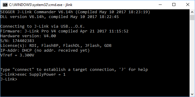
Example:
exec SupplyPower = 1
exec map reset
exec map exclude 0x10000000-0x3FFFFFFF
Changing J-Link Reset Strategy
The reset strategy can be changed by executing the RSetType = <ResetStrategy> J-Link Command String:
exec RSetType = 12
Connecting to a specific J-Link
It is possible to have multiple J-Links connected to the PC at the same time (for more information, see here. To connect to a specific J-Link in an automated way (no user interaction required), J-Link Commander needs to be told the S/N of the J-Link to connect to. This can be done via two different methods:
- Specify the S/N directly via command line. See -SelectEmuBySN above for more information.
- Specify "SelectEmuBySN <SN>" (without quotes) as first command in the J-Link command file that is passed to J-Link Commander via command line
Setup External CFI NOR Flash
J-Link Commander supports downloading bin files into external CFI flash memory. In the following, it is explained which steps are necessary to prepare J-Link Commander for download into external CFI flash memory based on a sample sequence for a ST STM32F103ZE device:
r
speed 1000
exec setcfiflash 0x64000000 - 0x64FFFFFF
exec setworkram 0x20000000 - 0x2000FFFF
w4 0x40021014, 0x00000114 // RCC_AHBENR, FSMC clock enable
w4 0x40021018, 0x000001FD // GPIOD~G clock enable
w4 0x40011400, 0xB4BB44BB // GPIOD low config, NOE, NWE => Output, NWAIT => Input
w4 0x40011404, 0xBBBBBBBB // GPIOD high config, A16-A18
w4 0x40011800, 0xBBBBBBBB // GPIOE low config, A19-A23
w4 0x40011804, 0xBBBBBBBB // GPIOE high config, D5-D12
w4 0x40011C00, 0x44BBBBBB // GPIOF low config, A0-A5
w4 0x40011C04, 0xBBBB4444 // GPIOF high config, A6-A9
w4 0x40012000, 0x44BBBBBB // GPIOG low config, A10-A15
w4 0x40012004, 0x444B4BB4 // GPIOG high config, NE2 => output
w4 0xA0000008, 0x00001059 // CS control reg 2, 16-bit, write enable, Type: NOR flash
w4 0xA000000C, 0x10000505 // CS2 timing reg (read access)
w4 0xA000010C, 0x10000505 // CS2 timing reg (write access)
speed 4000
mem 0x64000000,100
loadfile C:\STMB672_STM32F103ZE_TestBlinky.bin,0x64000000
mem 0x64000000,100
Command specifics
Verifybin command
The verifybin command in J-Link Commander executes a simple read of memory and compares the data against the data in the specified bin file. Note that *no* initialization of any flash interface etc. is done on this command. For external QSPI flash for example this means that the pins and the QSPI controller of the target MCU have to be already initialized etc. for this command to succeed. This is different for "loadbin" which may trigger a flash download implicitly where a flash loader is started that takes care of the initialization. Also note that executing a "loadbin" command in advance, does not guarantee that a "verifybin" succeeds because the loadbin commands restores the controller state after it is done. So if the QSPI controller and/or pins were not initialized before the "loadbin" command, they are not after it either. They are only available while "loadbin" is active.