Difference between revisions of "19-pin JTAG/SWD and Trace Connector"
(Created page with " thumb | left | 400px |J-Link 19-Pin Cortex-M Adapter / J-Trace 19-pin pinout<br> J-Trace provides a JTAG / SWD + Trace connector. This connector...") |
|||
| Line 1: | Line 1: | ||
| + | This article describes the 19-pin JTAG/SWD and Trace Connector, available on all J-Trace Pro. |
||
| + | __TOC__ |
||
| + | |||
| + | == Pinout == |
||
[[File:19pinTracePort.png | thumb | left | 400px |J-Link 19-Pin Cortex-M Adapter / J-Trace 19-pin pinout]]<br> |
[[File:19pinTracePort.png | thumb | left | 400px |J-Link 19-Pin Cortex-M Adapter / J-Trace 19-pin pinout]]<br> |
||
J-Trace provides a JTAG / SWD + Trace connector. |
J-Trace provides a JTAG / SWD + Trace connector. |
||
| Line 20: | Line 24: | ||
| '''8''' || NC / TDI || NC / Output || <ul><li>SWD: Not used. J-Link will ignore the signal on this pin when using SWD.</li><li>TDI: JTAG data input of target CPU. It is recommended that this pin is pulled to a defined state on the target board. Typically connected to TDI of the target CPU.</li></ul> |
| '''8''' || NC / TDI || NC / Output || <ul><li>SWD: Not used. J-Link will ignore the signal on this pin when using SWD.</li><li>TDI: JTAG data input of target CPU. It is recommended that this pin is pulled to a defined state on the target board. Typically connected to TDI of the target CPU.</li></ul> |
||
|- |
|- |
||
| − | | '''9''' || Not connected (TRST) || NC |
+ | | '''9''' || Not connected (TRST) || NC || By default, TRST is not connected, but the Cortex-M Adapter comes with a solder bridge (NR1) which allows TRST to be connected to pin 9 of the Cortex-M adapter. |
|- |
|- |
||
| '''10''' || nRESET || I/O || Target CPU reset signal. Typically connected to the RESET pin of the target CPU, which is typically called "nRST", "nRESET" or "RESET". This signal is an active low signal. |
| '''10''' || nRESET || I/O || Target CPU reset signal. Typically connected to the RESET pin of the target CPU, which is typically called "nRST", "nRESET" or "RESET". This signal is an active low signal. |
||
| Line 41: | Line 45: | ||
|} |
|} |
||
| + | == Connecting the target board == |
||
| − | |||
| + | J-Trace connects to the target board via a 19-pin trace cable. Alternatively J-Trace can be connected via the [[20-pin J-Link Connector]]. |
||
| − | ==== Connecting the target board ==== |
||
| + | {{Note|1= |
||
| − | J-Trace connects to the target board via a 19-pin trace cable. Alternatively J-Trace can be connected with a 20-pin JTAG cable. |
||
| − | + | Never connect 19- & 20-pin cable at the same time because this may lead to unstable debug and trace connections. |
|
[[File:190405_J-trace connection-final.jpg | none | 400px]] |
[[File:190405_J-trace connection-final.jpg | none | 400px]] |
||
| + | }} |
||
Latest revision as of 11:09, 4 January 2024
This article describes the 19-pin JTAG/SWD and Trace Connector, available on all J-Trace Pro.
Contents
Pinout

J-Trace provides a JTAG / SWD + Trace connector.
This connector is a 19-pin connector (0.05" / 1.27mm).
It connects to the target via an 1-1 cable.
The following table lists the J-Link / J-Trace SWD pinout.
| PIN | SIGNAL | TYPE | Description |
|---|---|---|---|
| 1 | VTref | Input | This is the target reference voltage. It is used to check if the target has power, to create the logic-level reference for the input comparators and to control the output logic levels to the target. It is normally fed from VDD of the target board and must not have a series resistor. |
| 2 | SWDIO / TMS | I/O / Output |
|
| 4 | SWCLK / TCK | Output |
|
| 6 | SWO / TDO | Input |
|
| --- | --- | --- | This pin (normally pin 7) is not existent on the 19-pin JTAG/SWD and Trace connector. |
| 8 | NC / TDI | NC / Output |
|
| 9 | Not connected (TRST) | NC | By default, TRST is not connected, but the Cortex-M Adapter comes with a solder bridge (NR1) which allows TRST to be connected to pin 9 of the Cortex-M adapter. |
| 10 | nRESET | I/O | Target CPU reset signal. Typically connected to the RESET pin of the target CPU, which is typically called "nRST", "nRESET" or "RESET". This signal is an active low signal. |
| 11 | 5V-Supply | Output | This pin can be used to supply power to the target hardware. Older J-Links may not be able to supply power on this pin. For more information about how to enable/disable the power supply, please refer to Target power supply. If you do not plan to supply power to the target via this pin it is recommended to connect it to GND. |
| 12 | TRACECLK | Input | Input trace clock. Trace clock = 1/2 CPU clock in most cases. |
| 13 | 5V-Supply | Output | This pin can be used to supply power to the target hardware. Older J-Links may not be able to supply power on this pin. For more information about how to enable/disable the power supply, please refer to Target power supply. If you do not plan to supply power to the target via this pin it is recommended to connect it to GND. |
| 14 | TRACEDATA[0] | Input | Input Trace data pin 0. |
| 16 | TRACEDATA[1] | Input | Input Trace data pin 1. |
| 18 | TRACEDATA[2] | Input | Input Trace data pin 2. |
| 20 | TRACEDATA[3] | Input | Input Trace data pin 3. |
| 3, 5, 15, 17, 19 | GND | Ground | GND pins connected to GND in J-Link. They should also be connected to GND in the target system. |
Connecting the target board
J-Trace connects to the target board via a 19-pin trace cable. Alternatively J-Trace can be connected via the 20-pin J-Link Connector.
Note:
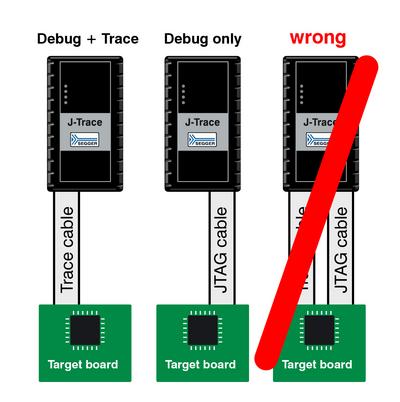
Never connect 19- & 20-pin cable at the same time because this may lead to unstable debug and trace connections.
