Difference between revisions of "GroupGets LoFive R1 1"
(→Preparing for J-Link) |
|||
| Line 15: | Line 15: | ||
The following guide will describe how the LoFive Board can be connected to your J-Link Base V10 or higher. Other J-Links might work as well but wiring might be slightly different. All needed information can be found in the probe related documentation. |
The following guide will describe how the LoFive Board can be connected to your J-Link Base V10 or higher. Other J-Links might work as well but wiring might be slightly different. All needed information can be found in the probe related documentation. |
||
| − | * The LoFive board does not come with the pin header populated so |
+ | * The LoFive board does not come with the pin header populated so first the pin headers need to be soldered to your board. |
* Now connect the board with e.g. jumperwires to your J-Link probe. |
* Now connect the board with e.g. jumperwires to your J-Link probe. |
||
* The following table shows how the Signals should be connected on both the board and [https://www.segger.com/products/debug-probes/j-link/technology/interface-description/ J-Link] side. |
* The following table shows how the Signals should be connected on both the board and [https://www.segger.com/products/debug-probes/j-link/technology/interface-description/ J-Link] side. |
||
Revision as of 14:59, 28 October 2019
Contents
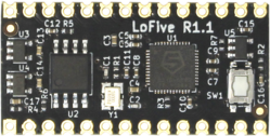
This article describes specifics for the GroupGets LoFive R1.1 board based on a SiFive FE310.
Minimum requirements
- Please note that RISC-V is not supported by older J-Link hardware models / revisions. Overview about which models / revisions support RISC-V
- Embedded Studio Version 4.30 or later
- J-Link software V6.52e or later
Preparing for J-Link
GroupGets LoFive R1.1 does not come with a standard debug connector but populates the debug JTAG signals on a 2x14 Arduino compatible pin header. Therefore, it can be manually wired in case J-Link shall be connected to it.
The following guide will describe how the LoFive Board can be connected to your J-Link Base V10 or higher. Other J-Links might work as well but wiring might be slightly different. All needed information can be found in the probe related documentation.
- The LoFive board does not come with the pin header populated so first the pin headers need to be soldered to your board.
- Now connect the board with e.g. jumperwires to your J-Link probe.
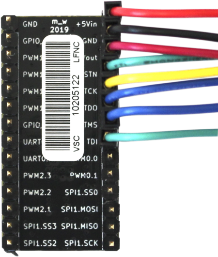
- The following table shows how the Signals should be connected on both the board and J-Link side.
| J-Link 20 pin debug interface | Pin on eval board Arduino header |
|---|---|
| Pin 1 (VTref) | +3.3Vout |
| Pin 4 (GND) | GND |
| Pin 5 (TDI) | TDI |
| Pin 7 (TMS) | TMS |
| Pin 9 (TCK) | TCK |
| Pin 13 (TDO) | TDO |
| Pin 15 (nRESET) | TRSTN |
| Pin 19 (5V-Supply) | +5Vin |
The resulting connection will then look like this:
- The use of the 5V-Supply pin on the J-Link is optional and can be used to power the target board through the J-Link. How is explained in the J-Link user guide UM08001. Alternatively you can connect an external 5 V power supply as well to the target board pin and use a second GND pin for the external power supply.
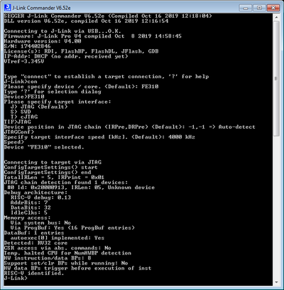
- Verify the Connection with e.g. J-Link Commander. The output should look as follows:
Debugging in SEGGER Embedded Studio
Example projects for SEGGER Embedded Studio
The following example project was created with the SEGGER Embedded Studio project wizard and runs out-of-the-box on the LoFive board. It is a simple Hello World sample and can be downloaded here:


