Difference between revisions of "SPC560D-Discovery Evalboard"
| Line 1: | Line 1: | ||
| − | The ST SPC560D-Discovery evaluation board needs to be setup manually before it can be debugged using an external J-link because by default, the on board debugger drives the debug pins. To isolate the on board debugger from the MCU, in order to make sure that it does not interact with the J-Link, the following solder bridges needs to be removed: |
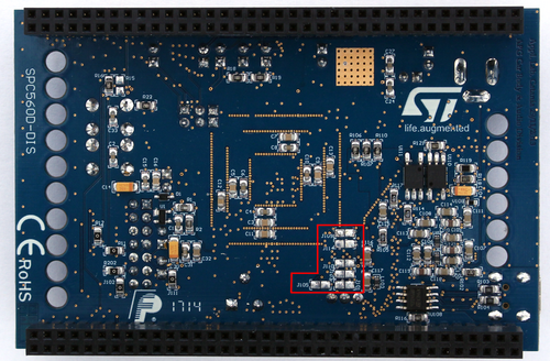
+ | The ST SPC560D-Discovery evaluation board needs to be setup manually before it can be debugged using an external J-link because by default, the on board debugger drives the debug pins. To isolate the on board debugger from the MCU, in order to make sure that it does not interact with the J-Link, the following solder bridges needs to be removed (see table / board image): |
| + | <table> |
||
| − | *J101 |
||
| + | <tr> |
||
| − | *J103 |
||
| + | <td valign="top">[[File:wiki-board-ST-SPC560D-DIS.png|500px]]</td> |
||
| − | *J105 |
||
| + | <td valign="top"></td> |
||
| − | *J109 |
||
| + | <td valign="top"> |
||
| − | *J111 |
||
| + | {| class="wikitable" |
||
| − | *J110 |
||
| + | |- |
||
| − | *J114 |
||
| − | + | ! SPC560D-Discovery |
|
| + | |- |
||
| + | | J101 |
||
| + | |- |
||
| + | | J103 |
||
| + | |- |
||
| + | | J105 |
||
| + | |- |
||
| + | | J109 |
||
| + | |- |
||
| + | | J110 |
||
| + | |- |
||
| + | | J111 |
||
| + | |- |
||
| + | | J14 |
||
| + | |} |
||
| + | </td> |
||
| + | </tr> |
||
| + | </table> |
||
Revision as of 11:51, 7 June 2016
The ST SPC560D-Discovery evaluation board needs to be setup manually before it can be debugged using an external J-link because by default, the on board debugger drives the debug pins. To isolate the on board debugger from the MCU, in order to make sure that it does not interact with the J-Link, the following solder bridges needs to be removed (see table / board image):
 |
|