ST STM32H5
ST STM32H5
Contents
The ST STM32H5 are Cortex-M33 based MCUs.
Flash Banks
Internal Flash
| Device | Base address | Size | J-Link Support |
|---|---|---|---|
| STM32H503EB | 0x08000000 | 128 KB | |
| STM32H503KB | 0x08000000 | 128 KB | |
| STM32H503CB | 0x08000000 | 128 KB | |
| STM32H503RB | 0x08000000 | 128 KB | |
| STM32H562AI | 0x08000000 | 2048 KB | |
| STM32H562II | 0x08000000 | 2048 KB | |
| STM32H562RI | 0x08000000 | 2048 KB | |
| STM32H562VI | 0x08000000 | 2048 KB | |
| STM32H562ZI | 0x08000000 | 2048 KB | |
| STM32H563AG | 0x08000000 | 2048 KB | |
| STM32H563AI | 0x08000000 | 2048 KB | |
| STM32H563IG | 0x08000000 | 2048 KB | |
| STM32H563II | 0x08000000 | 2048 KB | |
| STM32H563MI | 0x08000000 | 2048 KB | |
| STM32H563RG | 0x08000000 | 2048 KB | |
| STM32H563RI | 0x08000000 | 2048 KB | |
| STM32H563VG | 0x08000000 | 2048 KB | |
| STM32H563VI | 0x08000000 | 2048 KB | |
| STM32H563ZG | 0x08000000 | 2048 KB | |
| STM32H563ZI | 0x08000000 | 2048 KB | |
| STM32H573AI | 0x08000000 | 2048 KB | |
| STM32H573II | 0x08000000 | 2048 KB | |
| STM32H573MI | 0x08000000 | 2048 KB | |
| STM32H573RI | 0x08000000 | 2048 KB | |
| STM32H573VI | 0x08000000 | 2048 KB | |
| STM32H573ZI | 0x08000000 | 2048 KB |
ECC Flash
The flash is ECC protected. When programming code with J-Link, the device flash controller is set to automatically program the correct ECC values.
QSPI Flash
QSPI flash programming requires special handling compared to internal flash. For more information about this, please see the QSPI Flash Programming Support article.
| Device | Base address | Maximum size | Supported pin configuration |
|---|---|---|---|
| STM32H56x STM32H57x |
0x90000000 | 256MB | CLK@PF10_nCS@PG6_D0@PB1_D1@PD12_D2@PC2_D3@PD13_D4@NA_D5@NA_D6@NA_D7@NA CLK@PF10_nCS@PG6_D0@PF8_D1@PF9_D2@PC2_D3@PF6_D4@NA_D5@NA_D6@NA_D7@NA |
ECC RAM
The device family provides three RAM segments: SRAM1, SRAM2 and SRAM3.
J-Link uses SRAM1 during flash programming. SRAM2 and SRAM3 are ECC protected, while SRAM1 is not so no ECC initialization is necessary.
Device Specifc Handling
Reset
- The devices uses normal Cortex-M reset, no special handling necessary, like described here.
Evaluation Boards
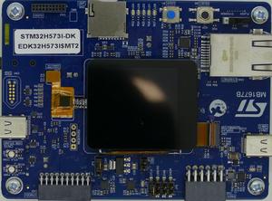
- ST STM32H573I-DK evaluation board: ST_STM32H573I-DK
Example Application
- ST STM32H573I-DK evaluation board: ST_STM32H573I-DK#Example_Project
Tracing on STM32H5 series
Tracing on ST STM32H573
Minimum requirements
In order to use trace on the ST STM32H573 MCU devices, the following minimum requirements have to be met:
- J-Link software version V7.86c or later
- Ozone V3.28e or later (if streaming trace and / or the sample project from below shall be used)
- J-Trace PRO for Cortex-M HW version V1.0 or later
- Tracepin connection like on the STM32H573I-DK board (See Specifics/Limitations for more information)
To rebuild the project our IDE Embedded Studio can be used. The recommended version to rebuild the projects is V6.30. But the examples are all prebuild and work out-of-the box with Ozone, so rebuilding is not necessary.
Streaming trace
The project below has been tested with the minimum requirements mentioned above and a ST STM32H573I-DK board.
- Example Project: ST_STM32H573_TracePins.zip
Specifics/Limitations
The STM32H573I-DK connects ESD diodes to the trace pins. This is not recommended and can cause issues on higher trace speeds. When designing your own trace board we recommend to not add such ESD diodes. Additionally on this eval board the signals TD0 and TD1 are shared with some JTAG signals via resistors R97 and R98. If you plan on using JTAG in parallel to the trace pins on the board make sure that the these resistors are removed. For more information see the boards reference manual.
Tested Hardware
Reference trace signal quality
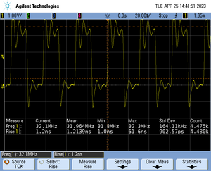
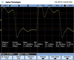
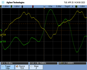
The following pictures show oscilloscope measurements of trace signals output by the "Tested Hardware" using the example project. All measurements have been performed using a Agilent InfiniiVision DSO7034B 350 MHz 2GSa/s oscilloscope and 1156A 1.5 GHz Active Probes. If your trace signals look similar on your trace hardware, chances are good that tracing will work out-of-the-box using the example project. More information about correct trace timing can be found at the following website.
Trace clock signal quality
The trace clock signal quality shows multiple trace clock cycles on the tested hardware as reference.
Rise time
The rise time of a signal shows the time needed for a signal to rise from logical 0 to logical 1. For this the values at 10% and 90% of the expected voltage level get used as markers. The following picture shows such a measurement for the trace clock signal.
Setup time
The setup time shows the relative setup time between a trace data signal and trace clock. The measurement markers are set at 50% of the expected voltage level respectively. The following picture shows such a measurement for the trace data signal 0 relative to the trace clock signal.


