Difference between revisions of "Using J-Link VCOM functionality"
(→Testing VCOM functionality and speed) |
(→Testing VCOM functionality and speed) |
||
| Line 32: | Line 32: | ||
This leads to the Rx pin receiving the sent data meaning that VCOM is active and working. |
This leads to the Rx pin receiving the sent data meaning that VCOM is active and working. |
||
* Create a loopback by connecting the Tx pin with the Rx pin. |
* Create a loopback by connecting the Tx pin with the Rx pin. |
||
| + | * Make sure pins VTref and GND are connected to J-Link. For testing we recommend VTref = 3.3 V. |
||
* Start a terminal application (e.g. HTerm) and establish a connection to the COM port. |
* Start a terminal application (e.g. HTerm) and establish a connection to the COM port. |
||
* Use an oscilloscope to visualize the signals sent via the Tx pin and the Rx pin. |
* Use an oscilloscope to visualize the signals sent via the Tx pin and the Rx pin. |
||
Revision as of 12:04, 30 May 2018
Contents
Enabling VCOM
In general, the VCOM feature can be disabled and enabled for debug probes which comes with support for it via J-Link Commander and J-Link Configurator.
Please note, that:
- VCOM can only be used when debugging via SWD target interface. Pin 5 = J-Link-Tx (out), Pin 17 = J-Link-Rx (in).
- Currently, only J-Link models with hardware version 9 or newer come with VCOM capabilities.
Via J-Link Configurator
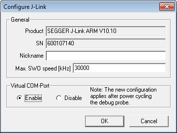
Start the J-Link Configurator and configure the device to enable VCOM functionality by double-clicking.
Under "Virtual COM-Port", choose "Enable" and click "OK". After that the device needs to be power cycled in order for VCOM to work.

Via J-Link Commander
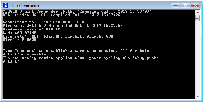
Start the J-Link Commander and enter "vcom enable". After that the device needs to be power cycled in order for VCOM to work.

Checking VCOM state
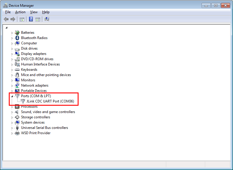
Checking if VCOM is active can be done by opening the device manager. Connected devices with VCOM functionality will be listed under "Ports (COM & LPT)".

Testing VCOM functionality and speed
The VCOM functionality can be tested for by simply connecting the Tx pin with the Rx pin - creating a loopback that way - and starting a terminal application. This leads to the Rx pin receiving the sent data meaning that VCOM is active and working.
- Create a loopback by connecting the Tx pin with the Rx pin.
- Make sure pins VTref and GND are connected to J-Link. For testing we recommend VTref = 3.3 V.
- Start a terminal application (e.g. HTerm) and establish a connection to the COM port.
- Use an oscilloscope to visualize the signals sent via the Tx pin and the Rx pin.
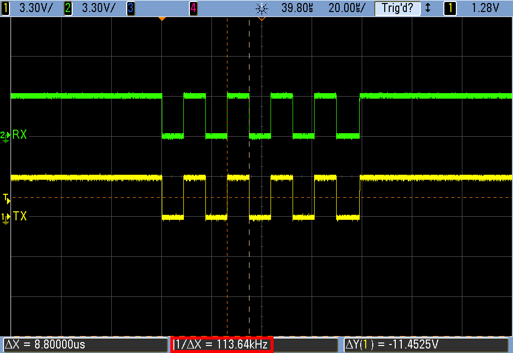
- Send data via VCOM using the given terminal application. Use the letter "U" (01010101 in binary) to create a regular square-wave signal.
The oscilloscope will show the same signal sequence for both, the Rx and the Tx pin, confirming the VCOM functionality.
The speed VCOM is operating at can also be determined with an oscilloscope, e.g. by measuring the duration of a single high state.
