Difference between revisions of "RTT"
(→Background mode) |
(→TELNET channel of J-Link software) |
||
| (25 intermediate revisions by 2 users not shown) | |||
| Line 14: | Line 14: | ||
An additional up (to host) channel can for example be used to send profiling or event tracing data |
An additional up (to host) channel can for example be used to send profiling or event tracing data |
||
(e.g. for [https://www.segger.com/products/development-tools/systemview/ SEGGER SystemView]). |
(e.g. for [https://www.segger.com/products/development-tools/systemview/ SEGGER SystemView]). |
||
| + | <div class="toclimit-3"> |
||
| − | |||
| − | <div class="toclimit-2"> |
||
__TOC__ |
__TOC__ |
||
</div> |
</div> |
||
| − | <br clear=all> |
||
| − | = How RTT works = |
+ | == How RTT works == |
| + | [[File:RTT_Schematics_Simple_tn.png | right]] |
||
| − | Real Time Transfer uses a SEGGER RTT Control Block structure in the target's memory to manage data reads and writes. |
||
| − | + | RTT uses a [[#RTT Control Block|SEGGER RTT Control Block]] structure and ring buffers for each configured direction of each channel, located in RAM. |
|
The maximum number of available channels can be configured at compile time and each buffer can be configured and added by the application at run time. |
The maximum number of available channels can be configured at compile time and each buffer can be configured and added by the application at run time. |
||
| − | Up and down buffers can be handled separately. |
+ | * Up and down buffers can be handled separately (see [[#RTT_Channels | RTT Channels]]). |
| − | Each channel can be configured to be blocking or non-blocking (see [[# |
+ | * Each channel can be configured to be blocking or non-blocking (see [[#Channel buffer configuration | Buffer configuration]]): |
| + | ** Blocking: Prevents data from being lost but may pause the application. |
||
| − | In blocking mode the application will wait when the buffer is full, until all memory could be written, resulting in a blocked application state but preventing data from getting lost. |
||
| − | + | ** Non-blocking: Excess information will be discarded, allowing the application to run in real-time, even when no debugger is connected. |
|
| + | The image on the right shows the simplified structure of RTT in the target. Each element is explained in the following. |
||
| − | This allows running in real-time, even when no debugger is connected. |
||
| + | === RTT Control Block === |
||
| − | The developer does not have to create a special debug version and the code can stay in place in a release application. |
||
| + | The RTT control block (CB) contains of multiple elements to allow RTT to work. It is located in RAM. |
||
| − | |||
| + | It always starts with an ID which is used to |
||
| − | == Locating the Control Block == |
||
| + | * make the CB (auto-)detectable in memory by a connected J-Link and |
||
| − | When RTT is active on the host computer, either by using RTT directly via an application like RTT Viewer or |
||
| + | * for a CB validity check. |
||
| − | by connecting via Telnet to an application which is using J-Link, like a debugger, |
||
| + | It is followed by the Buffer descriptors which hold all required RTT channel information. |
||
| − | J-Link automatically searches for the SEGGER RTT Control Block in the target's known RAM regions. |
||
| + | ==== Buffer Descriptors ==== |
||
| − | The RAM regions or the specific address of the Control Block can also be set via the host applications to |
||
| + | The buffer descriptors provide information about the ring buffers for each channel, used by J-Link to read information from and write information to the target. |
||
| − | speed up detection or if the block cannot be found automatically. |
||
| + | There may be any number of ''Up'' (Target -> Host) / ''Down'' (Host -> Target) '' Buffer Descriptors'' up to the maximum number of allowed channels.<br> |
||
| − | |||
| + | For Up buffers, |
||
| − | === Manual specification of the Control Block location === |
||
| + | * the Write Pointer is only written by the target and |
||
| − | While auto-detection of the RTT control block location works fine for most targets, |
||
| + | * the Read Pointer is only written by the debug probe (J-Link, Host). |
||
| − | it is always possible to manually specify either the exact location of the control block or |
||
| + | For Down buffers: |
||
| − | specific address range(s) J-Link shall search for a control block in. |
||
| − | + | * the Write Pointer is only written by the debug probe (J-Link, Host) and |
|
| + | * the Read Pointer is only written by the target. |
||
| − | * [[J-Link Command Strings#SetRTTAddr | SetRTTAddr]] |
||
| + | This assures that no race conditions can occur. |
||
| − | * [[J-Link Command Strings#SetRTTSearchRanges | SetRTTSearchRanges]] |
||
| + | When the Read and Write Pointers point to the same element, the buffer is empty. |
||
| − | Or via [[#SEGGER TELNET Config String | SEGGER TELNET Config String]] |
||
| + | === Buffers === |
||
| − | |||
| + | The ring buffers buffers are also located in RAM but are not part of the RTT CB. |
||
| − | == Internal structures == |
||
| + | The buffer size can be configured individually, for each channel & each direction. |
||
| − | [[File:RTT_Schematics_Simple_tn.png | none | 500px]] |
||
| + | The gray areas of the buffers in the image above show the areas containing valid data. |
||
| − | The image shows the simplified structure in the target. |
||
| + | === Requirements === |
||
| − | There may be any number of "Up Buffer Descriptors" (Target -> Host), as well as any number of "Down Buffer Descriptors" (Host -> Target). |
||
| − | Each buffer size can be configured individually.<br> |
||
| − | The gray areas in the buffers are the areas that contain valid data.<br> |
||
| − | For Up buffers, the Write Pointer is written by the target, the Read Pointer is written by the debug probe (J-Link, Host).<br> |
||
| − | When Read and Write Pointers point to the same element, the buffer is empty. |
||
| − | This assures there is never a race condition. |
||
| − | |||
| − | == Requirements == |
||
SEGGER RTT does not require any additional pin or hardware, despite a J-Link connected via the standard debug port to the target. |
SEGGER RTT does not require any additional pin or hardware, despite a J-Link connected via the standard debug port to the target. |
||
It does not require any configuration of the target or debugging environment and can even be used with varying target speeds.<br> |
It does not require any configuration of the target or debugging environment and can even be used with varying target speeds.<br> |
||
RTT can be used in parallel to a running debug session without intrusion, as well as without any IDE or debugger at all. |
RTT can be used in parallel to a running debug session without intrusion, as well as without any IDE or debugger at all. |
||
| + | === Performance === |
||
| − | |||
| − | == Performance == |
||
| − | [[File:RTT_SpeedComparison.png | thumb | right | 500px | RTT Speed comparison]] |
||
| − | <!--- Add Website image ---> |
||
The performance of SEGGER RTT is significantly higher than any other technology used to output data to a host PC. |
The performance of SEGGER RTT is significantly higher than any other technology used to output data to a host PC. |
||
An average line of text can be output in one microsecond or less. |
An average line of text can be output in one microsecond or less. |
||
| − | Basically only the time to do a single memcopy(). |
+ | Basically only the time to do a single <tt>memcopy()</tt>. |
| + | [[File:RTT_SpeedComparison.png | none ]] |
||
| − | <br clear=all> |
||
| − | == Memory footprint == |
+ | === Memory footprint === |
The RTT implementation code uses ~500 Bytes of ROM and 24 Bytes ID + 24 Bytes per channel for the control block in RAM. |
The RTT implementation code uses ~500 Bytes of ROM and 24 Bytes ID + 24 Bytes per channel for the control block in RAM. |
||
Each channel requires some memory for the buffer. |
Each channel requires some memory for the buffer. |
||
The recommended sizes are 1 kByte for up channels and 16 to 32 Bytes for down channels depending on the load of in- / output. |
The recommended sizes are 1 kByte for up channels and 16 to 32 Bytes for down channels depending on the load of in- / output. |
||
| + | == Control block detection == |
||
| − | = Modes = |
||
| + | RTT allows the J-Link to (auto-)detect the control block (CB) in a given RAM range. |
||
| − | SEGGER RTT can run in three different modes where some modes are not available on all MCUs or SEGGER Probes/Tools, but other modes are |
||
| + | Per default, auto-detection is used, but the user may also provide a specific control block address or a specific RAM range to be searched for the CB. |
||
| − | which then has an impact on the real time behavior of the device and/or the transfer speed. |
||
| + | When RTT is active on the host computer, either by using RTT directly via an application like [[J-Link RTT Viewer]] or by connecting via Telnet to an application which is using J-Link, like a debugger, |
||
| + | J-Link automatically searches for the SEGGER RTT Control Block in the target's RAM regions specified by the J-Link Software (auto-detection) and/or by the user (user selection). |
||
| + | === Auto-detection === |
||
| + | Per default, auto-detection is used to locate the RTT Control block (CB). This means that J-Link will search the RAM regions of the specified target known by the J-Link Software. |
||
| + | {{Note|1=For some MCUs, not all RAM regions are searched through when auto-detection is selected. Not all RAM regions may be available at all times depending on the targets state. Examples: |
||
| + | * The RAM may be configurable. |
||
| + | * The RAM may be unaccessable during certain MCU states (e.g. TrustZone secure/non-secure regions) |
||
| + | * The RAM may not be enabled by default or may be disabled by the user. |
||
| + | * The RAM may not be accessible via the selected MEM-AP (non Cortex-M targets only) |
||
| + | * ... |
||
| + | In such a case, the search range has to be added manually, or the CB has to be linked to another RAM section. |
||
| + | }} |
||
| + | === Manual specification of the Control Block location === |
||
| + | While auto-detection of the RTT control block location works fine in most cases, |
||
| + | it is always possible to manually specify either the exact location of the control block or |
||
| + | specific address range(s) J-Link shall search for a control block in.<br> |
||
| + | This can be done in multiple ways. For example: |
||
| + | * Using J-Link [[J-Link Command Strings]] e.g. in a [[J-Link_script_files#JLINK_ExecCommand()|J-Link Script file]]: |
||
| + | ** [[J-Link Command Strings#SetRTTAddr | SetRTTAddr]] |
||
| + | ** [[J-Link Command Strings#SetRTTSearchRanges | SetRTTSearchRanges]] |
||
| + | * Via the used Tool (if supported), e.g. in the configuration dialog of the [[J-Link RTT Viewer]] |
||
| + | * Via [[#TELNET_channel_of_J-Link_software | J-Link TELNET channel]] |
||
| + | == RTT Channels == |
||
| − | The three modes are |
||
| + | {{Note|1=This section refers to RTT '''channels''' and must not be confused with RTT Terminals.<br>For information about RTT Terminals, pleaser refer to the [[J-Link_RTT_Viewer#Using_"virtual"_Terminals_in_RTT | J-Link RTT Viewer article]].}} |
||
| − | {| class="wikitable" |
||
| + | An RTT channel consists of a configuration and a ring buffer used for data transfer in a specific direction (up: Target -> Host, down: Host -> Target). |
||
| + | === Channel configuration === |
||
| + | Up and down channels can be configured separately and individually: |
||
| + | * Channel Buffer size: Size of the channel buffer used for data transfer. |
||
| + | * Channel buffer mode (see below). |
||
| + | {{Note|1=RTT Channel 0 is somewhat special:<br> |
||
| + | It is configured on compile time and will be setup as soon as [[#SEGGER_RTT_Init()|SEGGER_RTT_Init()]] or any RTT write function is called. |
||
| + | This is done to provide an out of the box working experience, that does not require any manual setup. |
||
| + | * Channel 0 will be setup with the parameter defines mentioned in section [[#RTT_configuration|RTT configuration]]. |
||
| + | * Only the flags of Channel 0 can be manually (re)configured. All other configuration parameters are ignored when calling [[#SEGGER_RTT_ConfigDownBuffer()|SEGGER_RTT_ConfigDownBuffer()]] and [[#SEGGER_RTT_ConfigUpBuffer()|SEGGER_RTT_ConfigUpBuffer()]]. |
||
| + | * All other channels require their respective buffers to be setup manually using [[#SEGGER_RTT_ConfigDownBuffer()|SEGGER_RTT_ConfigDownBuffer()]] and [[#SEGGER_RTT_ConfigUpBuffer()|SEGGER_RTT_ConfigUpBuffer()]]. |
||
| + | }} |
||
| + | ==== Channel buffer modes ==== |
||
| + | The user may select one of 3 channel modes (one blocking mode and two non-blocking modes): |
||
| + | *In blocking mode the application will wait when the buffer is full, until all memory could be written, resulting in a blocked application state but preventing data from getting lost. |
||
| + | *In non-blocking mode only data which fits into the buffer, or none at all, will be written and the rest will be discarded. |
||
| + | This allows running in real-time, even when no debugger is connected, so the developer does not have to create a special debug version and the code can stay in place in a release application. |
||
| + | {| class="seggertable" |
||
| + | ! Define !! Meaning |
||
|- |
|- |
||
| + | | Blocking || The application will wait when the buffer is full, until all memory could be written, resulting in a blocked application state but preventing data from getting lost. |
||
| − | ! Mode |
||
| + | |- |
||
| − | ! Explanation |
||
| + | | Non-blocking, skip || If the up buffer has not enough space to hold all of the incoming data, all data is discarded. |
||
| − | ! Probe support |
||
| + | |- |
||
| − | |- <!-- ROW BACKGROUND MODE --> |
||
| + | | Non-blocking, trim || If the up buffer has not enough space to hold all of the incoming data, the available space is filled up with the incoming data and the rest is discarded. |
||
| − | | [[#Background mode | Background mode]] |
||
| + | |} |
||
| − | | It is the fastest mode with a transfer speed of up to ~2MB/s |
||
| + | See: [[#Channel buffer configuration | Channel buffer configuration]] |
||
| − | | |
||
| + | |||
| − | * All current J-Links / J-Trace Pro models. |
||
| + | == RTT operation Modes == |
||
| − | |- <!-- ROW LEGACY BACKGROUND MODE --> |
||
| + | SEGGER RTT can run in three different operating modes. |
||
| − | | [[#Legacy background mode | Legacy background mode]] |
||
| + | {{Note|1=Not to be mistaken with [[#Channel buffer configuration | Channel buffer configuration modes]].}} |
||
| − | | Legacy version of [[#Background mode | Background mode]], which does not come with handling on probe firmware side, leading to lower transfer speeds. |
||
| + | {| class="seggertable" |
||
| − | | |
||
| + | |- |
||
| + | ! Mode !! Explanation !! Probe support |
||
| + | |- |
||
| + | | [[#Background mode | Background mode]] || It is the fastest mode with a transfer speed of up to ~2MB/s || |
||
| + | *All current J-Links / J-Trace Pro models. |
||
| + | |- |
||
| + | | [[#Legacy background mode | Legacy background mode]] || Legacy version of [[#Background mode | Background mode]], which does not come with handling on probe firmware side, leading to lower transfer speeds. || |
||
* All current Flasher models |
* All current Flasher models |
||
* J-Link Base / Plus < V9 |
* J-Link Base / Plus < V9 |
||
* J-Link Pro / Ultra+ < V4 |
* J-Link Pro / Ultra+ < V4 |
||
* J-Trace Pro < V2 |
* J-Trace Pro < V2 |
||
| + | |- |
||
| − | |- <!-- ROW STOP MODE --> |
||
| − | | [[#Stop mode | Stop mode]] |
+ | | [[#Stop mode | Stop mode]] || Pseudo RTT mode. CPU is halted to read data. Introduced for CPUs that do not support Background-Access || |
| − | | Pseudo RTT mode. CPU is halted to read data. Introduced for CPUs that do not support Background-Access |
||
| − | | |
||
* All J-Link / J-Trace Pro / Flasher models |
* All J-Link / J-Trace Pro / Flasher models |
||
|} |
|} |
||
| + | === Background mode === |
||
| − | |||
| − | |||
| − | There are three different modes in |
||
| − | |||
| − | == Background mode == |
||
Same as [[#Legacy Background mode | Legacy Background mode]], but with additional implementation on Probe firmware side, which makes the transfer speed significantly higher (up to 2 MB/s). |
Same as [[#Legacy Background mode | Legacy Background mode]], but with additional implementation on Probe firmware side, which makes the transfer speed significantly higher (up to 2 MB/s). |
||
| + | === Legacy background mode === |
||
| − | |||
| − | == Legacy background mode == |
||
This is the mode which RTT was initially introduced with. In this mode, J-Link can access the memory of the target system while the MCU + application keeps running (background memory access), |
This is the mode which RTT was initially introduced with. In this mode, J-Link can access the memory of the target system while the MCU + application keeps running (background memory access), |
||
effectively not impacting the real time behavior of the application. In order to use this mode, the target MCU needs to support background memory accesses. |
effectively not impacting the real time behavior of the application. In order to use this mode, the target MCU needs to support background memory accesses. |
||
| + | ==== Cores with background mode support ==== |
||
| − | |||
| − | === Cores with background mode support === |
||
* Cortex-M. See [https://www.segger.com/products/debug-probes/j-link/technology/cpus-and-devices/overview-of-supported-cpus-and-devices/ list of supported cores] for an overview |
* Cortex-M. See [https://www.segger.com/products/debug-probes/j-link/technology/cpus-and-devices/overview-of-supported-cpus-and-devices/ list of supported cores] for an overview |
||
* Renesas RX based devices. |
* Renesas RX based devices. |
||
| − | * Cortex-A 32-bit (ARMv7-A) (Optional. See [[#Cortex-A specifics | Cortex-A specifics]] |
+ | * Cortex-A 32-bit (ARMv7-A) (Optional. See [[#Cortex-A specifics | Cortex-A specifics]]) |
| − | * Cortex-R 32-bit (ARMv7-R) (Optional. See [[#Cortex-R specifics | Cortex-R specifics]] |
+ | * Cortex-R 32-bit (ARMv7-R) (Optional. See [[#Cortex-R specifics | Cortex-R specifics]]) |
| − | * RISC-V (Optional. See [[#RISC-V specifics | RISC-V specifics]] |
+ | * RISC-V (Optional. See [[#RISC-V specifics | RISC-V specifics]]) |
| + | === Stop mode === |
||
| − | |||
| + | In this mode, J-Link temporarily halts the CPU (interrupts the execution of the target application) to access the memory and |
||
| − | == Stop mode == |
||
| + | continues operation automatically after the memory access is done. |
||
| − | This mode has been introduced in J-Link software V6.30 in order to also allow using RTT on devices / CPU architectures that do not support background memory accesses. This mode affects the real time behavior of the application but can still be used for most target applications. |
||
| + | The actual impact (halted time) on the real time behavior depends on the setup (target interface speed used, target interface used, length of JTAG chain, actual core that is used, ...).<br> |
||
| − | |||
| + | This mode has been introduced in J-Link software V6.30 in order to also allow using RTT on devices / CPU architectures that do not support background memory accesses. |
||
| − | In this mode, J-Link temporarily halts the CPU (interrupts the execution of the target application) to access the memory and continues operation automatically after the memory access is done. The actual impact (halted time) on the real time behavior depends on the setup (target interface speed used, target interface used, length of JTAG chain, actual core that is used, ...). |
||
| + | This mode affects the real time behavior of the application but can still be used for most target applications. |
||
| − | |||
| − | === Cores with stop mode support === |
+ | ==== Cores with stop mode support ==== |
* Cortex-A based devices |
* Cortex-A based devices |
||
* Cortex-R based devices |
* Cortex-R based devices |
||
* RISC-V based devices |
* RISC-V based devices |
||
| + | {{Note|1=It is recommended to only use this mode with target interface speeds of '''25 MHz or higher''' (J-Link ULTRA+, J-Link PRO) to keep the effect on the real time behavior as small as possible.<br>Refer to: [https://www.segger.com/products/debug-probes/j-link/models/model-overview/ J-Link model overview]}} |
||
| + | ==== Effect on real time behavior ==== |
||
| − | '''Note:''' It is recommended to only use this mode with target interface speeds of '''25 MHz or higher''' (J-Link ULTRA+, J-Link PRO) to keep the effect on the real time behavior as small as possible. [https://www.segger.com/products/debug-probes/j-link/models/model-overview/ J-Link model overview] |
||
| − | |||
| − | === Effect on real time behavior === |
||
| − | |||
Typical halted times for memory read accesses in stop mode with '''J-Link ULTRA+ @ 50 MHz''': |
Typical halted times for memory read accesses in stop mode with '''J-Link ULTRA+ @ 50 MHz''': |
||
<gallery> |
<gallery> |
||
| Line 141: | Line 167: | ||
File:Wiki-RTT_StopMode_JTAG_50MHz_1B.png|JTAG @ 50 MHz<br>4 bytes, ~418us |
File:Wiki-RTT_StopMode_JTAG_50MHz_1B.png|JTAG @ 50 MHz<br>4 bytes, ~418us |
||
</gallery> |
</gallery> |
||
| − | |||
Typical halted times for memory read accesses in stop mode with '''J-Link PLUS @ 15 MHz''': |
Typical halted times for memory read accesses in stop mode with '''J-Link PLUS @ 15 MHz''': |
||
<gallery> |
<gallery> |
||
| Line 148: | Line 173: | ||
</gallery> |
</gallery> |
||
| + | == Core specific considerations == |
||
| − | = Cortex-A specifics = |
||
| + | === Cortex-M specifics === |
||
| + | If the CPU implements caches: |
||
| + | * The RTT control block as well as all RTT buffers must start cache line aligned |
||
| + | * The RTT control block as well as all RTT buffers must be the multiple of a cache line in size |
||
| + | * In case the system provides multiple cache levels, the alignment and sizes of the control block and buffers must take the cache with the largest line size as the reference point. |
||
| + | * The control block and Up/Down buffer 0 are implicitly defined by SEGGER_RTT.c. So in order to make sure these fulfill the alignment requirements, SEGGER_RTT_CPU_CACHE_LINE_SIZE needs to be specified in case the cache line size is not <= 32-bytes in the used system. |
||
| + | * It is '''user application's responsibility''' to call a cache clean + invalidate on the RTT control block + all RTT buffers after segment init is complete but before RTT is used for the first time. A good time to do it is in main(). This makes sure that no cache line contains dirty RTT data / information which otherwise may be evicted to memory at some point during runtime. If embOS is used, it is usually safe to make sure that RTT is used after OS_InitHW() has been called, which performs a clean + invalidate of all cache lines. |
||
| + | * For RTT buffers that are specified and initialized at runtime (> index 0), the cache clean + invalidate needs to be performed just before calling any of the AllocBuffer() / ConfigBuffer() functions. |
||
| + | * In the application, the RTT control block, buffers and pointers to their names must be linked with virtual address == physical address |
||
| + | * The application must provide a uncached address alias to the memory where the control block + buffers are located in. The control block as well as all buffers need to be accessible via that uncached address alias. |
||
| + | === Cortex-A specifics === |
||
* RTT background memory accesses are performed via either an AHB-AP or an AXI-AP |
* RTT background memory accesses are performed via either an AHB-AP or an AXI-AP |
||
* The presence of an AHB-AP and AXI-AP is optional and depends on the actual MCU (if the vendor implemented them) |
* The presence of an AHB-AP and AXI-AP is optional and depends on the actual MCU (if the vendor implemented them) |
||
| Line 155: | Line 191: | ||
* It is strongly recommended to place the RTT control block and buffers in internal memory, not external one. On Cortex-A based systems, external address space is usually very sensitive and can easily cause lockups etc. in case it is accessed before it has been initialized (e.g. DDR controller init done etc.). As J-Link has no information about when external memory space init is done, there is a potential for RTT accesses from the J-Link side before the external memory is available. |
* It is strongly recommended to place the RTT control block and buffers in internal memory, not external one. On Cortex-A based systems, external address space is usually very sensitive and can easily cause lockups etc. in case it is accessed before it has been initialized (e.g. DDR controller init done etc.). As J-Link has no information about when external memory space init is done, there is a potential for RTT accesses from the J-Link side before the external memory is available. |
||
* AHB/AXI-AP accesses behave like DMA accesses and bypass CPU L1 / L2 etc. caches |
* AHB/AXI-AP accesses behave like DMA accesses and bypass CPU L1 / L2 etc. caches |
||
| − | * If the CPU implements caches |
+ | * If the CPU implements caches, see [[#Cortex-M specifics | Cortex-M specifics]]. |
| + | ==== Cortex-A MCU examples ==== |
||
| − | ** The RTT control block as well as all RTT buffers must start cache line aligned |
||
| − | ** The RTT control block as well as all RTT buffers must be the multiple of a cache line in size |
||
| − | ** In case the system provides multiple cache levels, the alignment and sizes of the control block and buffers must take the cache with the largest line size as the reference point. |
||
| − | ** The control block and Up/Down buffer 0 are implicitly defined by SEGGER_RTT.c. So in order to make sure these fulfill the alignment requirements, RTT_CACHE_LINE_SIZE needs to be specified in case the cache line size is not <= 32-bytes in the used system. |
||
| − | ** It is '''user application's responsibility''' to call a cache clean + invalidate on the RTT control block + all RTT buffers after segment init is complete but before RTT is used for the first time. A good time to do it is in main(). This makes sure that no cache line contains dirty RTT data / information which otherwise may be evicted to memory at some point during runtime. If embOS is used, it is usually safe to make sure that RTT is used after OS_InitHW() has been called, which performs a clean + invalidate of all cache lines. |
||
| − | ** For RTT buffers that are specified and initialized at runtime (> index 0), the cache clean + invalidate needs to be performed just before calling any of the AllocBuffer() / ConfigBuffer() functions. |
||
| − | ** In the application, the RTT control block, buffers and pointers to their names must be linked with virtual address == physical address |
||
| − | ** The application must provide a uncached address alias to the memory where the control block + buffers are located in. The control block as well as all buffers need to be accessible via that uncached address alias. |
||
| − | |||
| − | == Cortex-A MCU examples == |
||
Sample MCUs for which RTT is supported out-of-the-box: |
Sample MCUs for which RTT is supported out-of-the-box: |
||
* Xilinx Zynq 7000 series, Cortex-A9 based (RTT supported since V6.85b) |
* Xilinx Zynq 7000 series, Cortex-A9 based (RTT supported since V6.85b) |
||
* NXP i.MX6Solo series, Cortex-A9 based, device name pattern: MCIMX6Sx (RTT supported since V6.85d) |
* NXP i.MX6Solo series, Cortex-A9 based, device name pattern: MCIMX6Sx (RTT supported since V6.85d) |
||
| + | Example project for [https://www.segger.com/evaluate-our-software/segger/empower-zynq/ emPower Zynq board]: |
||
| − | |||
| − | + | * [[Media:emPower_Zynq_RTTExample.zip | Project download]] |
|
| + | * Requirements: |
||
| − | |||
| + | ** [https://www.segger.com/products/development-tools/embedded-studio/ SEGGER Embedded Studio] V5.10a or later |
||
| − | Requirements: |
||
| + | ** J-Link software V6.85b or later |
||
| − | * [https://www.segger.com/products/development-tools/embedded-studio/ SEGGER Embedded Studio] V5.10a or later |
||
| + | === Cortex-R specifics === |
||
| − | * J-Link software V6.85b or later |
||
| − | |||
| − | = Cortex-R specifics = |
||
For RTT on Cortex-R, the same applies as for [[#Cortex-A specifics | Cortex-A specifics]]. |
For RTT on Cortex-R, the same applies as for [[#Cortex-A specifics | Cortex-A specifics]]. |
||
| + | === RISC-V specifics === |
||
| − | |||
| − | = RISC-V specifics = |
||
* RTT background memory accesses are performed either via via RISC-V system bus access (SBA) or via AHB/AXI-AP. |
* RTT background memory accesses are performed either via via RISC-V system bus access (SBA) or via AHB/AXI-AP. |
||
* The presence of SBA support is optional and depends on the actual MCU. |
* The presence of SBA support is optional and depends on the actual MCU. |
||
* AHB/AXI-AP access is only possible for setups where the RISC-V core is behind an ARM CoreSight DAP. |
* AHB/AXI-AP access is only possible for setups where the RISC-V core is behind an ARM CoreSight DAP. |
||
| + | ==== Support via SBA ==== |
||
| − | |||
| − | == Support via SBA == |
||
* No specific setup is needed. J-Link detects the presence of SBA support automatically and can use RTT out-of-the-box. |
* No specific setup is needed. J-Link detects the presence of SBA support automatically and can use RTT out-of-the-box. |
||
| + | ==== Support via MEM-AP ==== |
||
| − | |||
| − | == Support via AP == |
||
* The presence of an AHB-AP and AXI-AP is optional and depends on the actual MCU (if the vendor implemented them) |
* The presence of an AHB-AP and AXI-AP is optional and depends on the actual MCU (if the vendor implemented them) |
||
* Support for this access method starts with J-Link software V7.50 |
* Support for this access method starts with J-Link software V7.50 |
||
| Line 198: | Line 220: | ||
** The RTT control block as well as all RTT buffers must be the multiple of a cache line in size |
** The RTT control block as well as all RTT buffers must be the multiple of a cache line in size |
||
** In case the system provides multiple cache levels, the alignment and sizes of the control block and buffers must take the cache with the largest line size as the reference point. |
** In case the system provides multiple cache levels, the alignment and sizes of the control block and buffers must take the cache with the largest line size as the reference point. |
||
| − | ** The control block and Up/Down buffer 0 are implicitly defined by SEGGER_RTT.c. So in order to make sure these fulfill the alignment requirements, |
+ | ** The control block and Up/Down buffer 0 are implicitly defined by SEGGER_RTT.c. So in order to make sure these fulfill the alignment requirements, SEGGER_RTT_CPU_CACHE_LINE_SIZE needs to be specified in case the cache line size is not <= 32-bytes in the used system. |
** It is '''user application's responsibility''' to call a cache clean + invalidate on the RTT control block + all RTT buffers after segment init is complete but before RTT is used for the first time. A good time to do it is in main(). This makes sure that no cache line contains dirty RTT data / information which otherwise may be evicted to memory at some point during runtime. If embOS is used, it is usually safe to make sure that RTT is used after OS_InitHW() has been called, which performs a clean + invalidate of all cache lines. |
** It is '''user application's responsibility''' to call a cache clean + invalidate on the RTT control block + all RTT buffers after segment init is complete but before RTT is used for the first time. A good time to do it is in main(). This makes sure that no cache line contains dirty RTT data / information which otherwise may be evicted to memory at some point during runtime. If embOS is used, it is usually safe to make sure that RTT is used after OS_InitHW() has been called, which performs a clean + invalidate of all cache lines. |
||
** For RTT buffers that are specified and initialized at runtime (> index 0), the cache clean + invalidate needs to be performed just before calling any of the AllocBuffer() / ConfigBuffer() functions. |
** For RTT buffers that are specified and initialized at runtime (> index 0), the cache clean + invalidate needs to be performed just before calling any of the AllocBuffer() / ConfigBuffer() functions. |
||
| Line 204: | Line 226: | ||
** The application must provide a uncached address alias to the memory where the control block + buffers are located in. The control block as well as all buffers need to be accessible via that uncached address alias. |
** The application must provide a uncached address alias to the memory where the control block + buffers are located in. The control block as well as all buffers need to be accessible via that uncached address alias. |
||
| + | == Implementation == |
||
| − | = RTT Communication = |
||
| − | Communication with the RTT implementation on the target can be done with different applications. |
||
| − | The functionality can even be integrated into custom applications using the [https://www.segger.com/products/debug-probes/j-link/technology/j-link-sdk/ J-Link SDK].<br> |
||
| − | Using RTT in the target application is made easy. The implementation code is freely available for download and |
||
| − | can be integrated into any existing application. To communicate via RTT any J-Link can be used.<br> |
||
| − | A simple way to communicate via RTT is to create a connection to localhost:19021 with a Telnet client or similar, |
||
| − | while a connection to J-Link (e.g. via a debug session) is active. In this case, the RTT Channel can be set via a [[#SEGGER TELNET Config String | SEGGER TELNET Config String]]. |
||
| − | The default channel is channel 0 (Terminal)<br> |
||
| − | The [[J-Link Software and Documentation Pack]] comes with some more advanced applications, which demonstrates RTT functionality for different purposes. |
||
| − | |||
| − | == RTT Viewer == |
||
| − | See [[J-Link RTT Viewer]]. |
||
| − | |||
| − | == RTT Client == |
||
| − | J-Link RTT Client acts as a Telnet client, but automatically tries to reconnect to a J-Link connection when a debug session is closed.<br> |
||
| − | The J-Link RTT Client is part of the [[J-Link Software and Documentation Pack | J-Link Software Pack]] for Windows, Linux and macOS and can be used for simple RTT use cases. |
||
| − | |||
| − | '''Note:'''<br> |
||
| − | The J-Link RTT Client does not open a debug connection to the device via J-Link. However, an active debug connection is required for RTT to work. |
||
| − | Therefore, the RTT Client can '''only be used in combination''' with a J-Link tool that establishes an active debug connection (e.g. [[J-Link Commander]] or [[J-Link GDB Server]]). |
||
| − | |||
| − | === Command line options === |
||
| − | {| class="wikitable" |
||
| − | ! Command !! Explanation |
||
| − | |- |
||
| − | | -? || Shows commandline options |
||
| − | |- |
||
| − | | -LocalEcho || 1 = Enables - / 0 = Disables local echo |
||
| − | |- |
||
| − | | -rtttelnetport <Port> || Sets the RTT telnet port to <Port> |
||
| − | |} |
||
| − | |||
| − | == RTT Logger == |
||
| − | With J-Link RTT Logger, data from all RTT Up-Channels can be read and logged to a file. |
||
| − | This channel can for example be used to send performance analysis data to the host.<br> |
||
| − | J-Link RTT Logger opens a dedicated connection to J-Link and can be used stand-alone, without running a debugger.<br> |
||
| − | The application is part of the [[J-Link Software and Documentation Pack]] for Windows, Linux and macOS.<br> |
||
| − | The source of the J-Link RTT Logger is part of the [https://www.segger.com/products/debug-probes/j-link/technology/j-link-sdk/ J-Link SDK] and |
||
| − | can be used as a starting point to integrate RTT in other PC applications, like debuggers. |
||
| − | |||
| − | === Command line options === |
||
| − | All command line options expect a value (except for "-?"). |
||
| − | {| class="wikitable" |
||
| − | ! Command !! Explanation |
||
| − | |- |
||
| − | | -? || Shows commandline options |
||
| − | |- |
||
| − | | -Device <DeviceName> || Sets target device to <DeviceName> |
||
| − | |- |
||
| − | | -if <Interface> || Sets target interface to <Interface> |
||
| − | |- |
||
| − | | -Speed <SpeedInKHZ> || Sets speed to <SpeedInKHZ> |
||
| − | |- |
||
| − | | -USB <SN> || Connects to J-Link with serial number <SN> via USB (0 == autodetect / device selection dialog). |
||
| − | |- |
||
| − | | -IP <IPAddr> || Connects to J-Link with IP <IPAddr> via TCP/IP. |
||
| − | |- |
||
| − | | -RTTAddress <RTTAddress> || Sets RTT address to <RTTAddress> |
||
| − | |- |
||
| − | | -RTTSearchRanges "<Ranges>" || Sets RTT search ranges to <Ranges>. Please note that quotations are required. |
||
| − | |- |
||
| − | | -RTTChannel <RTTChannel> || Sets RTT channel to <RTTChannel> |
||
| − | |} |
||
| − | |||
| − | == RTT in other host applications == |
||
| − | RTT can also be integrated in any other PC application like a debugger or a data visualizer in either of two ways: |
||
| − | * The application can establish a socket connection to the RTT Telnet Server which is opened on localhost:19021 when a J-Link connection is active (See [[#TELNET channel of J-Link software | TELNET channel of J-Link software]]). |
||
| − | * The application creates its own connection to J-Link and uses the J-Link RTT API which is part of the [https://www.segger.com/products/debug-probes/j-link/technology/j-link-sdk/ J-Link SDK] to directly configure and use RTT. |
||
| − | |||
| − | = Implementation = |
||
The SEGGER RTT implementation code is written in ANSI C and can be integrated into any embedded application by simply adding the available sources.<br> |
The SEGGER RTT implementation code is written in ANSI C and can be integrated into any embedded application by simply adding the available sources.<br> |
||
RTT can be used via a simple and easy to use API. |
RTT can be used via a simple and easy to use API. |
||
| − | It is even possible to override the standard printf() functions to be used with RTT. |
+ | It is even possible to override the standard <tt>printf()</tt> functions to be used with RTT. |
Using RTT reduces the time taken for output to a minimum and allows printing debug information to the host computer while the application is performing time critical real time tasks. |
Using RTT reduces the time taken for output to a minimum and allows printing debug information to the host computer while the application is performing time critical real time tasks. |
||
| − | The implementation code also includes a simple version of printf() which can be used to write formatted strings via RTT. |
+ | The implementation code also includes a simple version of <tt>printf()</tt> which can be used to write formatted strings via RTT. |
| − | It is smaller than most standard library printf() implementations and does not require heap and only a configurable amount of stack. |
+ | It is smaller than most standard library <tt>printf()</tt> implementations and does not require heap and only a configurable amount of stack. |
The SEGGER RTT implementation is fully configurable at compile time with pre-processor defines. |
The SEGGER RTT implementation is fully configurable at compile time with pre-processor defines. |
||
The number of channels and the size of the default channels can be set. |
The number of channels and the size of the default channels can be set. |
||
| − | Reading and writing can be made task-safe with definable Lock() and Unlock() routines. |
+ | Reading and writing can be made task-safe with definable <tt>Lock()</tt> and <tt>Unlock()</tt> routines. |
| + | |||
| + | The sources are available at two locations: |
||
| + | * As part of the [[J-Link Software and Documentation Pack]], under <tt>%InstDir%/Samples/RTT</tt> |
||
| + | * At the [https://github.com/SEGGERMicro/RTT SEGGER GitHub] |
||
| + | |||
| + | === RTT initialization === |
||
| + | {{Note|1=The RTT implementation expects the RAM location of the control block in either of two states: |
||
| + | # 0 initialized, when RTT has not been setup yet. This is the default case for most users. |
||
| + | # With an already setup control block. This is to allow a shared control block for multi application setups, such as bootloader + main application. |
||
| + | In any other case, [[#SEGGER_RTT_Init()|SEGGER_RTT_Init()]] '''must''' first be called before calling any other RTT function!}} |
||
| − | == API functions == |
+ | === API functions === |
The following API functions are available in the RTT Implementation. |
The following API functions are available in the RTT Implementation. |
||
To use them <tt>SEGGER_RTT.h</tt> has to be included in the calling sources. |
To use them <tt>SEGGER_RTT.h</tt> has to be included in the calling sources. |
||
| − | {| class=" |
+ | {| class="seggertable" |
! API functions |
! API functions |
||
|- |
|- |
||
| Line 319: | Line 282: | ||
|} |
|} |
||
| − | === SEGGER_RTT_ConfigDownBuffer() === |
+ | ==== SEGGER_RTT_ConfigDownBuffer() ==== |
Configure or add a down buffer by specifying its name, size and flags. |
Configure or add a down buffer by specifying its name, size and flags. |
||
| − | ==== Syntax ==== |
+ | ===== Syntax ===== |
<tt>int SEGGER_RTT_ConfigDownBuffer (unsigned BufferIndex, const char* sName, char* pBuffer, int BufferSize, int Flags);</tt> |
<tt>int SEGGER_RTT_ConfigDownBuffer (unsigned BufferIndex, const char* sName, char* pBuffer, int BufferSize, int Flags);</tt> |
||
| − | {| class=" |
+ | {| class="seggertable" |
! Parameter !! Meaning |
! Parameter !! Meaning |
||
|- |
|- |
||
| Line 334: | Line 297: | ||
| <tt>BufferSize</tt> || Size of the buffer in Bytes. |
| <tt>BufferSize</tt> || Size of the buffer in Bytes. |
||
|- |
|- |
||
| − | | <tt>Flags</tt> || Flags of the channel (blocking or non-blocking). |
+ | | <tt>Flags</tt> || Flags of the channel (blocking or non-blocking).<br>Flags[31:24]: Used for validity check, must be zero.<br>Flags[23:2]: Reserved for future use.<br>Flags[1:0]: RTT operating mode. |
|} |
|} |
||
| − | ==== Return value ==== |
+ | ===== Return value ===== |
| − | {| class=" |
+ | {| class="seggertable" |
! Value !! Meaning |
! Value !! Meaning |
||
|- |
|- |
||
| Line 344: | Line 307: | ||
| < 0 || Error |
| < 0 || Error |
||
|} |
|} |
||
| − | ==== Example ==== |
+ | ===== Example ===== |
<source lang="c">// |
<source lang="c">// |
||
// Configure down buffer 1 |
// Configure down buffer 1 |
||
| Line 350: | Line 313: | ||
SEGGER_RTT_ConfigDownBuffer(1, "DataIn", &abDataIn[0], sizeof(abDataIn), |
SEGGER_RTT_ConfigDownBuffer(1, "DataIn", &abDataIn[0], sizeof(abDataIn), |
||
SEGGER_RTT_MODE_NO_BLOCK_SKIP);</source> |
SEGGER_RTT_MODE_NO_BLOCK_SKIP);</source> |
||
| − | ==== Additional information ==== |
+ | ===== Additional information ===== |
Once a buffer is configured only the flags of the buffer should be changed. |
Once a buffer is configured only the flags of the buffer should be changed. |
||
| − | === SEGGER_RTT_ConfigUpBuffer() === |
+ | ==== SEGGER_RTT_ConfigUpBuffer() ==== |
Configure or add an up buffer by specifying its name, size and flags. |
Configure or add an up buffer by specifying its name, size and flags. |
||
| − | ==== Syntax ==== |
+ | ===== Syntax ===== |
<tt>int SEGGER_RTT_ConfigUpBuffer (unsigned BufferIndex, const char* sName, char* pBuffer, int BufferSize, int Flags);</tt> |
<tt>int SEGGER_RTT_ConfigUpBuffer (unsigned BufferIndex, const char* sName, char* pBuffer, int BufferSize, int Flags);</tt> |
||
| − | {| class=" |
+ | {| class="seggertable" |
! Parameter !! Meaning |
! Parameter !! Meaning |
||
|- |
|- |
||
| Line 368: | Line 331: | ||
| BufferSize || Size of the buffer in Bytes. |
| BufferSize || Size of the buffer in Bytes. |
||
|- |
|- |
||
| − | | Flags || Flags of the channel (blocking or non-blocking). |
+ | | Flags || Flags of the channel (blocking or non-blocking).<br>Flags[31:24]: Used for validity check, must be zero.<br>Flags[23:2]: Reserved for future use.<br>Flags[1:0]: RTT operating mode. |
|} |
|} |
||
| − | ==== Return value ==== |
+ | ===== Return value ===== |
| − | {| class=" |
+ | {| class="seggertable" |
! Value !! Meaning |
! Value !! Meaning |
||
|- |
|- |
||
| Line 378: | Line 341: | ||
| < 0 || Error |
| < 0 || Error |
||
|} |
|} |
||
| − | ==== Example ==== |
+ | ===== Example ===== |
<source lang="c">// |
<source lang="c">// |
||
// Configure up buffer 1 to work in blocking mode |
// Configure up buffer 1 to work in blocking mode |
||
| Line 384: | Line 347: | ||
SEGGER_RTT_ConfigUpBuffer(1, "DataOut", &abDataOut[0], sizeof(abDataOut), |
SEGGER_RTT_ConfigUpBuffer(1, "DataOut", &abDataOut[0], sizeof(abDataOut), |
||
SEGGER_RTT_MODE_BLOCK_IF_FIFO_FULL);</source> |
SEGGER_RTT_MODE_BLOCK_IF_FIFO_FULL);</source> |
||
| − | ==== Additional information ==== |
+ | ===== Additional information ===== |
Once a buffer is configured only the flags of the buffer should be changed. |
Once a buffer is configured only the flags of the buffer should be changed. |
||
| − | === SEGGER_RTT_GetKey() === |
+ | ==== SEGGER_RTT_GetKey() ==== |
Reads one character from SEGGER RTT buffer 0. |
Reads one character from SEGGER RTT buffer 0. |
||
Host has previously stored data there. |
Host has previously stored data there. |
||
| − | ==== Syntax ==== |
+ | ===== Syntax ===== |
<tt>int SEGGER_RTT_GetKey (void);</tt> |
<tt>int SEGGER_RTT_GetKey (void);</tt> |
||
| − | ==== Return value ==== |
+ | ===== Return value ===== |
| − | {| class=" |
+ | {| class="seggertable" |
! Value !! Meaning |
! Value !! Meaning |
||
|- |
|- |
||
| Line 400: | Line 363: | ||
| < 0 || No character available (empty buffer). |
| < 0 || No character available (empty buffer). |
||
|} |
|} |
||
| − | ==== Example ==== |
+ | ===== Example ===== |
<source lang="c">int c; |
<source lang="c">int c; |
||
c = SEGGER_RTT_GetKey(); |
c = SEGGER_RTT_GetKey(); |
||
| Line 407: | Line 370: | ||
}</source> |
}</source> |
||
| − | === SEGGER_RTT_HasKey() === |
+ | ==== SEGGER_RTT_HasKey() ==== |
Checks if at least one character for reading is available in SEGGER RTT buffer. |
Checks if at least one character for reading is available in SEGGER RTT buffer. |
||
| − | ==== Syntax ==== |
+ | ===== Syntax ===== |
<tt>int SEGGER_RTT_HasKey (void);</tt> |
<tt>int SEGGER_RTT_HasKey (void);</tt> |
||
| − | ==== Return value ==== |
+ | ===== Return value ===== |
| − | {| class=" |
+ | {| class="seggertable" |
! Value !! Meaning |
! Value !! Meaning |
||
|- |
|- |
||
| Line 419: | Line 382: | ||
| 0 || No characters are available to be read. |
| 0 || No characters are available to be read. |
||
|} |
|} |
||
| − | ==== Example ==== |
+ | ===== Example ===== |
<source lang="c">if (SEGGER_RTT_HasKey()) { |
<source lang="c">if (SEGGER_RTT_HasKey()) { |
||
int c = SEGGER_RTT_GetKey(); |
int c = SEGGER_RTT_GetKey(); |
||
}</source> |
}</source> |
||
| − | === SEGGER_RTT_Init() === |
+ | ==== SEGGER_RTT_Init() ==== |
Initializes the RTT Control Block. |
Initializes the RTT Control Block. |
||
| − | ==== Syntax ==== |
+ | ===== Syntax ===== |
<tt>void SEGGER_RTT_Init (void);</tt> |
<tt>void SEGGER_RTT_Init (void);</tt> |
||
| − | ==== Additional information ==== |
+ | ===== Additional information ===== |
| − | Should be used in RAM targets, at start of the application. |
+ | * Should be used in RAM targets, at start of the application. |
| + | * '''Must''' be the first SEGGER_RTT_* call in case the RTT CB is linked to a non 0 initialized RAM section. |
||
| − | === SEGGER_RTT_printf() === |
+ | ==== SEGGER_RTT_printf() ==== |
Send a formatted string to the host. |
Send a formatted string to the host. |
||
| − | ==== Syntax ==== |
+ | ===== Syntax ===== |
<tt>int SEGGER_RTT_printf (unsigned BufferIndex, const char * sFormat, ...)</tt> |
<tt>int SEGGER_RTT_printf (unsigned BufferIndex, const char * sFormat, ...)</tt> |
||
| − | {| class=" |
+ | {| class="seggertable" |
! Parameter !! Meaning |
! Parameter !! Meaning |
||
|- |
|- |
||
| Line 442: | Line 406: | ||
| sFormat || Pointer to format string, followed by arguments for conversion. |
| sFormat || Pointer to format string, followed by arguments for conversion. |
||
|} |
|} |
||
| − | ==== Return value ==== |
+ | ===== Return value ===== |
| − | {| class=" |
+ | {| class="seggertable" |
! Value !! Meaning |
! Value !! Meaning |
||
|- |
|- |
||
| Line 450: | Line 414: | ||
| < 0 || Error. |
| < 0 || Error. |
||
|} |
|} |
||
| − | ==== Example ==== |
+ | ===== Example ===== |
<source lang="c">SEGGER_RTT_printf(0, "SEGGER RTT Sample. Uptime: %.10dms.", /*OS_Time*/ 890912); |
<source lang="c">SEGGER_RTT_printf(0, "SEGGER RTT Sample. Uptime: %.10dms.", /*OS_Time*/ 890912); |
||
// Formatted output on channel 0: SEGGER RTT Sample. Uptime: 890912ms.</source> |
// Formatted output on channel 0: SEGGER RTT Sample. Uptime: 890912ms.</source> |
||
| − | ==== Additional information ==== |
+ | ===== Additional information ===== |
<ol> |
<ol> |
||
<li> |
<li> |
||
Conversion specifications have following syntax:<br> |
Conversion specifications have following syntax:<br> |
||
<tt>%[flags][FieldWidth][.Precision]ConversionSpecifier%</tt> |
<tt>%[flags][FieldWidth][.Precision]ConversionSpecifier%</tt> |
||
| + | {{Note|1=Flags, FieldWidth and Precision will be ignored for all but the following specifiers: d, u, x}} |
||
</li> |
</li> |
||
<li> |
<li> |
||
Supported flags: |
Supported flags: |
||
| − | {| class=" |
+ | {| class="seggertable" |
! Flag !! Meaning |
! Flag !! Meaning |
||
|- |
|- |
||
| Line 473: | Line 438: | ||
<li> |
<li> |
||
Supported conversion specifiers: |
Supported conversion specifiers: |
||
| − | {| class=" |
+ | {| class="seggertable" |
| − | ! Conversion |
+ | ! Conversion<br>specifier !! Meaning |
|- |
|- |
||
| − | | c || Print the argument as one char |
+ | | c || Print the argument as one char |
|- |
|- |
||
| − | | d || Print the argument as a signed integer |
+ | | d || Print the argument as a signed integer |
|- |
|- |
||
| − | | u || Print the argument as an unsigned integer |
+ | | u || Print the argument as an unsigned integer |
|- |
|- |
||
| − | | x || Print the argument as an hexadecimal integer |
+ | | x || Print the argument as an hexadecimal integer |
|- |
|- |
||
| − | | s || Print the string pointed to by the argument |
+ | | s || Print the string pointed to by the argument |
|- |
|- |
||
| − | | p || Print the argument as an 8-digit hexadecimal integer. (Argument shall be a pointer to void.) |
+ | | p || Print the argument as an 8-digit hexadecimal integer. (Argument shall be a pointer to void.) |
|} |
|} |
||
</li> |
</li> |
||
</ol> |
</ol> |
||
| − | === SEGGER_RTT_Read() === |
+ | ==== SEGGER_RTT_Read() ==== |
Read characters from any RTT down channel which have been previously stored by the host. |
Read characters from any RTT down channel which have been previously stored by the host. |
||
| − | ==== Syntax ==== |
+ | ===== Syntax ===== |
<tt>unsigned SEGGER_RTT_Read (unsigned BufferIndex, char* pBuffer, unsigned BufferSize);</tt> |
<tt>unsigned SEGGER_RTT_Read (unsigned BufferIndex, char* pBuffer, unsigned BufferSize);</tt> |
||
| − | {| class=" |
+ | {| class="seggertable" |
! Parameter !! Meaning |
! Parameter !! Meaning |
||
|- |
|- |
||
| Line 504: | Line 469: | ||
| BufferSize || Number of bytes available in the buffer. |
| BufferSize || Number of bytes available in the buffer. |
||
|} |
|} |
||
| − | ==== Return value ==== |
+ | ===== Return value ===== |
| − | {| class=" |
+ | {| class="seggertable" |
! Value !! Meaning |
! Value !! Meaning |
||
|- |
|- |
||
| >= 0 || Number of bytes that have been read. |
| >= 0 || Number of bytes that have been read. |
||
|} |
|} |
||
| − | ==== Example ==== |
+ | ===== Example ===== |
<source lang="c">char acIn[4]; |
<source lang="c">char acIn[4]; |
||
unsigned NumBytes = sizeof(acIn); |
unsigned NumBytes = sizeof(acIn); |
||
| Line 518: | Line 483: | ||
}</source> |
}</source> |
||
| − | === SEGGER_RTT_SetTerminal() === |
+ | ==== SEGGER_RTT_SetTerminal() ==== |
Set the "virtual" terminal to send following data on channel 0. |
Set the "virtual" terminal to send following data on channel 0. |
||
| − | ==== Syntax ==== |
+ | ===== Syntax ===== |
<tt>void SEGGER_RTT_SetTerminal(char TerminalId);</tt> |
<tt>void SEGGER_RTT_SetTerminal(char TerminalId);</tt> |
||
| − | {| class=" |
+ | {| class="seggertable" |
! Parameter !! Meaning |
! Parameter !! Meaning |
||
|- |
|- |
||
| Line 528: | Line 493: | ||
|} |
|} |
||
| − | ==== Example ==== |
+ | ===== Example ===== |
<source lang="c">// |
<source lang="c">// |
||
// Send a string to terminal 1 which is used as error out. |
// Send a string to terminal 1 which is used as error out. |
||
| Line 535: | Line 500: | ||
SEGGER_RTT_WriteString(0, "ERROR: Buffer overflow"); |
SEGGER_RTT_WriteString(0, "ERROR: Buffer overflow"); |
||
SEGGER_RTT_SetTerminal(0); // Reset to standard terminal</source> |
SEGGER_RTT_SetTerminal(0); // Reset to standard terminal</source> |
||
| − | ==== Additional information ==== |
+ | ===== Additional information ===== |
All following data which is sent via channel 0 will be printed on the set terminal until the next change. |
All following data which is sent via channel 0 will be printed on the set terminal until the next change. |
||
| − | === SEGGER_RTT_TerminalOut() === |
+ | ==== SEGGER_RTT_TerminalOut() ==== |
Send one string to a specific "virtual" terminal. |
Send one string to a specific "virtual" terminal. |
||
| − | ==== Syntax ==== |
+ | ===== Syntax ===== |
<tt>int SEGGER_RTT_TerminalOut (char TerminalID, const char* s);</tt> |
<tt>int SEGGER_RTT_TerminalOut (char TerminalID, const char* s);</tt> |
||
| − | {| class=" |
+ | {| class="seggertable" |
! Parameter !! Meaning |
! Parameter !! Meaning |
||
|- |
|- |
||
| Line 549: | Line 514: | ||
| s || Pointer to 0-terminated string to be sent. |
| s || Pointer to 0-terminated string to be sent. |
||
|} |
|} |
||
| − | ==== Return value ==== |
+ | ===== Return value ===== |
| − | {| class=" |
+ | {| class="seggertable" |
! Value !! Meaning |
! Value !! Meaning |
||
|- |
|- |
||
| Line 557: | Line 522: | ||
| < 0 || Error. |
| < 0 || Error. |
||
|} |
|} |
||
| − | ==== Example ==== |
+ | ===== Example ===== |
<source lang="c">// |
<source lang="c">// |
||
// Sent a string to terminal 1 without changing the standard terminal. |
// Sent a string to terminal 1 without changing the standard terminal. |
||
// |
// |
||
SEGGER_RTT_TerminalOut(1, "ERROR: Buffer overflow.");</source> |
SEGGER_RTT_TerminalOut(1, "ERROR: Buffer overflow.");</source> |
||
| − | ==== Additional information ==== |
+ | ===== Additional information ===== |
SEGGER_RTT_TerminalOut does not affect following data which is sent via channel 0. |
SEGGER_RTT_TerminalOut does not affect following data which is sent via channel 0. |
||
| − | === SEGGER_RTT_Write() === |
+ | ==== SEGGER_RTT_Write() ==== |
Send data to the host on an RTT channel. |
Send data to the host on an RTT channel. |
||
| − | ==== Syntax ==== |
+ | ===== Syntax ===== |
<tt>unsigned SEGGER_RTT_Write (unsigned BufferIndex, const char* pBuffer, unsigned NumBytes);</tt> |
<tt>unsigned SEGGER_RTT_Write (unsigned BufferIndex, const char* pBuffer, unsigned NumBytes);</tt> |
||
| − | {| class=" |
+ | {| class="seggertable" |
! Parameter !! Meaning |
! Parameter !! Meaning |
||
|- |
|- |
||
| Line 578: | Line 543: | ||
| NumBytes || Number of bytes to send. |
| NumBytes || Number of bytes to send. |
||
|} |
|} |
||
| − | ==== Return value ==== |
+ | ===== Return value ===== |
| − | {| class=" |
+ | {| class="seggertable" |
! Value !! Meaning |
! Value !! Meaning |
||
|- |
|- |
||
| Line 586: | Line 551: | ||
| < 0 || Error. |
| < 0 || Error. |
||
|} |
|} |
||
| − | ==== Additional information ==== |
+ | ===== Additional information ===== |
With SEGGER_RTT_Write() all kinds of data, not only printable ones can be sent. |
With SEGGER_RTT_Write() all kinds of data, not only printable ones can be sent. |
||
| − | === SEGGER_RTT_WaitKey() === |
+ | ==== SEGGER_RTT_WaitKey() ==== |
Waits until at least one character is available in SEGGER RTT buffer 0. |
Waits until at least one character is available in SEGGER RTT buffer 0. |
||
Once a character is available, it is read and returned. |
Once a character is available, it is read and returned. |
||
| − | ==== Syntax ==== |
+ | ===== Syntax ===== |
<tt>int SEGGER_RTT_WaitKey (void);</tt> |
<tt>int SEGGER_RTT_WaitKey (void);</tt> |
||
| − | ==== Return value ==== |
+ | ===== Return value ===== |
| − | {| class=" |
+ | {| class="seggertable" |
! Value !! Meaning |
! Value !! Meaning |
||
|- |
|- |
||
| >= 0 || Character which has been read (0 - 255). |
| >= 0 || Character which has been read (0 - 255). |
||
|} |
|} |
||
| − | ==== Example ==== |
+ | ===== Example ===== |
<source lang="c">int c = 0; |
<source lang="c">int c = 0; |
||
do { |
do { |
||
| Line 606: | Line 571: | ||
} while (c != 'c');</source> |
} while (c != 'c');</source> |
||
| − | === SEGGER_RTT_WriteString() === |
+ | ==== SEGGER_RTT_WriteString() ==== |
Write a 0-terminated string to an up channel via RTT. |
Write a 0-terminated string to an up channel via RTT. |
||
| − | ==== Syntax ==== |
+ | ===== Syntax ===== |
<tt>unsigned SEGGER_RTT_WriteSting (unsigned BufferIndex, const char* s);</tt> |
<tt>unsigned SEGGER_RTT_WriteSting (unsigned BufferIndex, const char* s);</tt> |
||
| − | {| class=" |
+ | {| class="seggertable" |
!! Parameter !! Meaning |
!! Parameter !! Meaning |
||
|- |
|- |
||
| Line 617: | Line 582: | ||
| s || Pointer to 0-terminated string to be sent. |
| s || Pointer to 0-terminated string to be sent. |
||
|} |
|} |
||
| − | ==== Return value ==== |
+ | ===== Return value ===== |
| − | {| class=" |
+ | {| class="seggertable" |
! Value !! Meaning |
! Value !! Meaning |
||
|- |
|- |
||
| >= 0 || Number of bytes which have been sent. |
| >= 0 || Number of bytes which have been sent. |
||
|} |
|} |
||
| − | ==== Example ==== |
+ | ===== Example ===== |
<source lang="c">SEGGER_RTT_WriteString(0, "Hello World from your target.\n");</source> |
<source lang="c">SEGGER_RTT_WriteString(0, "Hello World from your target.\n");</source> |
||
| − | === SEGGER_RTT_GetAvailWriteSpace() === |
+ | ==== SEGGER_RTT_GetAvailWriteSpace() ==== |
Returns the number of bytes available in the ring buffer. |
Returns the number of bytes available in the ring buffer. |
||
| − | ==== Syntax ==== |
+ | ===== Syntax ===== |
<tt>unsigned SEGGER_RTT_GetAvailWriteSpace (unsigned BufferIndex);</tt> |
<tt>unsigned SEGGER_RTT_GetAvailWriteSpace (unsigned BufferIndex);</tt> |
||
| − | {| class=" |
+ | {| class="seggertable" |
! Parameter !! Meaning |
! Parameter !! Meaning |
||
|- |
|- |
||
| BufferIndex || Index of the up channel that should be checked for space. |
| BufferIndex || Index of the up channel that should be checked for space. |
||
|} |
|} |
||
| − | ==== Return value ==== |
+ | ===== Return value ===== |
| − | {| class=" |
+ | {| class="seggertable" |
! Value !! Meaning |
! Value !! Meaning |
||
|- |
|- |
||
| >= 0 || Number of bytes that are free in the selected up buffer. |
| >= 0 || Number of bytes that are free in the selected up buffer. |
||
|} |
|} |
||
| − | ==== Example ==== |
+ | ===== Example ===== |
<source lang="c">unsigned NumBytesFree; |
<source lang="c">unsigned NumBytesFree; |
||
NumBytesFree = SEGGER_RTT_GetAvailWriteSpace(0);</source> |
NumBytesFree = SEGGER_RTT_GetAvailWriteSpace(0);</source> |
||
| − | == Configuration defines == |
+ | === Configuration defines === |
| − | === RTT configuration === |
+ | ==== RTT configuration ==== |
| − | {| class=" |
+ | {| class="seggertable" |
! Define / Routine !! Meaning |
! Define / Routine !! Meaning |
||
|- |
|- |
||
| Line 668: | Line 633: | ||
|} |
|} |
||
| − | === Channel buffer configuration === |
+ | ==== Channel buffer configuration ==== |
| − | {| class=" |
+ | {| class="seggertable" |
! Define !! Meaning |
! Define !! Meaning |
||
|- |
|- |
||
| Line 682: | Line 647: | ||
* The buffer configuration '''only effects the target device buffers, not the host buffers'''. |
* The buffer configuration '''only effects the target device buffers, not the host buffers'''. |
||
| − | === Color control sequences === |
+ | ==== Color control sequences ==== |
| − | {| class=" |
+ | {| class="seggertable" |
! Configuration !! Meaning |
! Configuration !! Meaning |
||
|- |
|- |
||
| Line 725: | Line 690: | ||
|} |
|} |
||
| − | = ARM Cortex - Background memory access = |
+ | == ARM Cortex - Background memory access == |
On ARM Cortex targets, background memory access necessary for RTT is performed via a so-called AHB-AP which is similar to a DMA but exclusively accessible by the debug probe. |
On ARM Cortex targets, background memory access necessary for RTT is performed via a so-called AHB-AP which is similar to a DMA but exclusively accessible by the debug probe. |
||
While on Cortex-M targets there is always an AHB-AP present, on Cortex-A and Cortex-R targets this is an optional component. |
While on Cortex-M targets there is always an AHB-AP present, on Cortex-A and Cortex-R targets this is an optional component. |
||
| Line 732: | Line 697: | ||
This is done via the following [[J-Link Command Strings | J-Link Command string]]: [[J-Link Command Strings#CORESIGHT_SetIndexAHBAPToUse | CORESIGHT_SetIndexAHBAPToUse]].<br> |
This is done via the following [[J-Link Command Strings | J-Link Command string]]: [[J-Link Command Strings#CORESIGHT_SetIndexAHBAPToUse | CORESIGHT_SetIndexAHBAPToUse]].<br> |
||
| − | = Example code = |
+ | == Example code == |
<source lang="c">/********************************************************************* |
<source lang="c">/********************************************************************* |
||
* SEGGER Microcontroller GmbH * |
* SEGGER Microcontroller GmbH * |
||
| Line 761: | Line 726: | ||
int Cnt = 0; |
int Cnt = 0; |
||
| + | SEGGER_RTT_Init(void); |
||
SEGGER_RTT_WriteString(0, "Hello World from SEGGER!\n"); |
SEGGER_RTT_WriteString(0, "Hello World from SEGGER!\n"); |
||
do { |
do { |
||
| Line 779: | Line 745: | ||
/*************************** End of file ****************************/</source> |
/*************************** End of file ****************************/</source> |
||
| + | == RTT Communication == |
||
| − | = TELNET channel of J-Link software = |
||
| + | Communication with the RTT implementation on the target can be done with different applications. |
||
| − | The J-Link software provides a TELNET channel on port '''19021''' to allow easy access to RTT data from a separate 3rd party application that may run in parallel to the debug session. The TELNET channel is very simple to use and basically all it requires is to open a local TCP/IP connection to port 19021 and start to receive data. |
||
| + | The functionality can even be integrated into custom applications using the [https://www.segger.com/products/debug-probes/j-link/technology/j-link-sdk/ J-Link SDK].<br> |
||
| − | |||
| + | Using RTT in the target application is made easy. The implementation code is freely available for download and |
||
| − | == SEGGER TELNET Config String == |
||
| + | can be integrated into any existing application. To communicate via RTT any J-Link can be used.<br> |
||
| − | After establishing a connection via TELNET, the user has '''100ms''' to send a SEGGER TELNET Config String from the host system (e.g. via J-Link RTT Client or putty).<br> |
||
| + | A simple way to communicate via RTT is to create a connection to localhost:19021 with a Telnet client or similar, |
||
| − | Sending a SEGGER TELNET config string '''after 100ms have passed''' since the TELNET connection was established has no effect<br> |
||
| + | while a connection to J-Link (e.g. via a debug session) is active. In this case, the RTT Channel can be set via a [[#SEGGER TELNET Config String | SEGGER TELNET Config String]]. |
||
| − | and is treated the same as if it was RTT data sent from the host.<br> |
||
| + | The default channel is channel 0 (Terminal)<br> |
||
| − | Additionally, sending a SEGGER TELNET config string is optional, meaning that RTT will function correctly even without sending such a config string. |
||
| + | The [[J-Link Software and Documentation Pack]] comes with some more advanced applications, which demonstrates RTT functionality for different purposes: |
||
| − | |||
| + | * [[J-Link RTT Viewer]]. |
||
| − | === Syntax === |
||
| + | * [[J-Link RTT Client]]. |
||
| − | The config string syntax is the following: |
||
| + | * [[J-Link RTT Logger]] |
||
| − | $$SEGGER_TELNET_ConfigStr=<Command>[;<Command>][...]$$ |
||
| + | === Integrating RTT in host applications === |
||
| − | Each <Command> is setup as follows: |
||
| + | RTT can also be integrated in any other PC application like a debugger or a data visualizer in either of two ways: |
||
| − | <CommandName>;[<Value1>;<Value2>;...] |
||
| + | * The application can establish a socket connection to the RTT Telnet Server which is opened on localhost:19021 when a J-Link connection is active (See [[#TELNET channel of J-Link software | TELNET channel of J-Link software]]). |
||
| − | |||
| + | * The application creates its own connection to J-Link and uses the J-Link RTT API which is part of the [https://www.segger.com/products/debug-probes/j-link/technology/j-link-sdk/ J-Link SDK] to directly configure and use RTT. |
||
| − | === Config String command list === |
||
| − | {| class="wikitable" |
||
| − | |- |
||
| − | ! Command !! Description |
||
| − | |- |
||
| − | | [[#RTTCh | RTTCh;<ChannelNo>]] || Sets the RTT Channel to <ChannelNo> |
||
| − | |- |
||
| − | | [[#SetRTTAddr | SetRTTAddr;<Addr>]] || Sets the RTT Control Block address to <CtrlBlkAddr> |
||
| − | |- |
||
| − | | [[#SetRTTSearchRanges | SetRTTSearchRanges;<Range>]] || Sets the RTT Control Block search range to <Range(s)> |
||
| − | |- |
||
| − | |} |
||
| − | |||
| − | ==== RTTCh ==== |
||
| − | Sets the RTT Channel to <ChannelNo>. |
||
| − | ===== Syntax: ===== |
||
| − | RTTCh;<ChannelNo> |
||
| − | ===== Example ===== |
||
| − | $$SEGGER_TELNET_ConfigStr=RTTCh;1$$ |
||
| − | |||
| − | ==== SetRTTAddr ==== |
||
| − | Sets the RTT Control Block address to <CtrlBlkAddr> |
||
| − | ===== Syntax: ===== |
||
| − | SetRTTAddr;<Addr> |
||
| − | ===== Example ===== |
||
| − | $$SEGGER_TELNET_ConfigStr=SetRTTAddr;0x20000000$$ |
||
| − | |||
| − | ==== SetRTTSearchRanges ==== |
||
| − | Sets the RTT Control Block search range(s) to <Range(s)> |
||
| − | ===== Syntax: ===== |
||
| − | SetRTTSearchRanges;<Range(s)> |
||
| − | <Range(s)> = <RangeStartInHex> <RangeSizeInHex>[, <Range1StartInHex> <Range1SizeInHex>, ...] |
||
| − | ===== Example ===== |
||
| − | $$SEGGER_TELNET_ConfigStr=SetRTTSearchRanges;0x10000000 0x1000, 0x20000000 0x1000$$ |
||
| − | |||
| − | === Config String multiple commands example === |
||
| − | $$SEGGER_TELNET_ConfigStr=RTTCh;1;SetRTTAddr;0x20000000;$$ |
||
| − | |||
| − | == Sample code - TELNET client == |
||
| − | In the following, come sample code is given for writing a TELNET client that connects to the TELNET channel of the J-Link software. |
||
| + | == TELNET channel of J-Link software == |
||
| − | === The blocking way === |
||
| + | The J-Link software provides a TELNET-like channel on a localhost port (default: '''19021''') to allow easy access to RTT data from a separate 3rd party application that may run in parallel to the debug session. |
||
| − | Without any special options, a call to connect() of the host OS socket API is blocking until either a connection is established or a timeout is reached. This is the default way but has the disadvantage that the thread calling connect() is blocked and connect exit itself during the timeout counts down, in case an application close request comes in during the count down. |
||
| + | The TELNET channel is very simple to use and basically all it requires is to open a local TCP/IP connection to the TELNET port and start to receive (or send) data. |
||
| − | Complete contents of the SYS_ functions can be retrieved from the source code delivered with the [https://shop.segger.com/J_Link_SDK_p/8.08.06.htm J-Link SDK] |
||
| − | void TELNET_Client(void) { |
||
| − | int t; |
||
| − | int r; |
||
| − | SYS_SOCKET_HANDLE hSock; |
||
| − | char ac[512]; |
||
| − | |||
| − | do { |
||
| − | r = -1; |
||
| − | printf("Waiting for connection...\n"); |
||
| − | do { |
||
| − | hSock = SYS_SOCKET_OpenTCP(); |
||
| − | if (hSock == SYS_SOCKET_INVALID_HANDLE) { // Failed to open socket? => Something basic in the OS failed. Done... |
||
| − | goto ErrHandler; |
||
| − | } |
||
| − | r = SYS_SOCKET_Connect(hSock, 0x7F000001, 19021); // Connect to 127.0.0.1, port 19021 |
||
| − | if (r == 0) { |
||
| − | break; |
||
| − | } |
||
| − | // |
||
| − | // We need to close a socket and reopen a new one if a timeout occurs, |
||
| − | // otherwise the OS sometimes does not recognize that |
||
| − | // the port became available in between |
||
| − | // |
||
| − | SYS_SOCKET_Close(hSock); |
||
| − | } while (r <= 0); |
||
| − | // |
||
| − | // Read from TELNET connection |
||
| − | // |
||
| − | do { |
||
| − | r = SYS_SOCKET_Receive(hSock, ac, sizeof(ac) - 1); |
||
| − | if (r <= 0) { // 0 == Connection gracefully closed by server. < 0 == Some other error |
||
| − | break; |
||
| − | } |
||
| − | ac[r] = 0; |
||
| − | printf("%s", ac); |
||
| − | } while (1); |
||
| − | SYS_SOCKET_Close(hSock); |
||
| − | } while (1); |
||
| − | ErrHandler: |
||
| − | } |
||
| + | For further information, please refer to: [[J-Link RTT TELNET Channel]]. |
||
| − | === The non-blocking way === |
||
| − | It is possible to configure a socket to be non-blocking, so that a call to connect() immediately returns, allowing the thread to remain responsive. In order to check if a connection has been established successfully, the socket status needs to be checked periodically. |
||
| − | Complete contents of the SYS_ functions can be retrieved from the source code delivered with the [https://shop.segger.com/J_Link_SDK_p/8.08.06.htm J-Link SDK] |
||
| − | |||
| − | void TELNET_Client(void) { |
||
| − | int t; |
||
| − | int r; |
||
| − | SYS_SOCKET_HANDLE hSock; |
||
| − | char ac[512]; |
||
| − | |||
| − | do { |
||
| − | r = -1; |
||
| − | printf("Waiting for connection...\n"); |
||
| − | do { |
||
| − | hSock = SYS_SOCKET_OpenTCP(); |
||
| − | if (hSock == SYS_SOCKET_INVALID_HANDLE) { // Failed to open socket? => Something basic in the OS failed. Done... |
||
| − | goto ErrHandler; |
||
| − | } |
||
| − | SYS_SOCKET_SetNonBlocking(hSock); // Make sure that connect() returns immediately |
||
| − | SYS_SOCKET_Connect(hSock, 0x7F000001, 19021); // Connect to 127.0.0.1, port 19021 |
||
| − | r = SYS_SOCKET_IsWriteable(hSock, 10); // Returns if socket is ready to send data (connection established) |
||
| − | if (r > 0) { |
||
| − | SYS_SOCKET_SetBlocking(hSock); // Make sure it is blocking again, to calls to recv() and send() block |
||
| − | break; |
||
| − | } |
||
| − | // |
||
| − | // We need to close a socket and reopen a new one if a timeout occurs, |
||
| − | // otherwise the OS sometimes does not recognize that |
||
| − | // the port became available in between |
||
| − | // |
||
| − | SYS_SOCKET_Close(hSock); |
||
| − | } while (r <= 0); |
||
| − | // |
||
| − | // Read from TELNET connection |
||
| − | // |
||
| − | do { |
||
| − | r = SYS_SOCKET_Receive(hSock, ac, sizeof(ac) - 1); |
||
| − | if (r <= 0) { // 0 == Connection gracefully closed by server. < 0 == Some other error |
||
| − | break; |
||
| − | } |
||
| − | ac[r] = 0; |
||
| − | printf("%s", ac); |
||
| − | } while (1); |
||
| − | SYS_SOCKET_Close(hSock); |
||
| − | } while (1); |
||
| − | ErrHandler: |
||
| − | } |
||
| − | = Low-power modes = |
+ | == Low-power modes == |
Many CPU cores support low-power modes to save power while waiting for an event or interrupt. On Cortex-M for example this is achieved by executing the WFI and WFE instructions. Unfortunately, the exact behavior during low-power modes is depending on the actual device (two devices from different vendors incorporating the same Cortex-M core may behave different). |
Many CPU cores support low-power modes to save power while waiting for an event or interrupt. On Cortex-M for example this is achieved by executing the WFI and WFE instructions. Unfortunately, the exact behavior during low-power modes is depending on the actual device (two devices from different vendors incorporating the same Cortex-M core may behave different). |
||
* Some devices disable the whole debug unit during low-power modes, causing J-Link to lose the connection to the device. |
* Some devices disable the whole debug unit during low-power modes, causing J-Link to lose the connection to the device. |
||
| Line 936: | Line 777: | ||
'''Solution:''' When using RTT, make sure that low-power modes are '''not used'''. |
'''Solution:''' When using RTT, make sure that low-power modes are '''not used'''. |
||
| − | = Samples = |
+ | == Samples == |
* [[STM32F3#RTT | RTT on STM32F3]] |
* [[STM32F3#RTT | RTT on STM32F3]] |
||
* [[STM32F4#RTT | RTT on STM32F4]] |
* [[STM32F4#RTT | RTT on STM32F4]] |
||
* [[STM32H7#RTT | RTT on STM32H7]] |
* [[STM32H7#RTT | RTT on STM32H7]] |
||
| − | = Troubleshooting = |
+ | == Troubleshooting == |
If you have trouble getting RTT to work with your setup, please try the following: |
If you have trouble getting RTT to work with your setup, please try the following: |
||
* Make sure the target device supports RTT. For more information, refer to [[#Modes | Modes]] |
* Make sure the target device supports RTT. For more information, refer to [[#Modes | Modes]] |
||
| Line 954: | Line 795: | ||
** The address of the RTT Control block can be set using [[J-Link Command Strings | J-Link Command Strings]], or when using J-Link RTT Viewer, in the Configuration Dialog. |
** The address of the RTT Control block can be set using [[J-Link Command Strings | J-Link Command Strings]], or when using J-Link RTT Viewer, in the Configuration Dialog. |
||
** Address ranges for J-Link to look for the RTT Control block can be set using [[J-Link Command Strings | J-Link Command Strings]], or when using J-Link RTT Viewer, in the Configuration Dialog. |
** Address ranges for J-Link to look for the RTT Control block can be set using [[J-Link Command Strings | J-Link Command Strings]], or when using J-Link RTT Viewer, in the Configuration Dialog. |
||
| + | * Make sure that the correct RTT channel used by the target application (e.g. J-Link RTT Viewer and J-Link RTT Client only supports data communication via channel 0). |
||
| − | = FAQ = |
+ | == FAQ == |
<ul> |
<ul> |
||
| + | <li>'''Q:''' How does J-Link find the RTT buffer?</li> |
||
| − | <li> |
||
| + | <li>'''A:''' There are two ways: If the debugger (IDE) knows the address of the SEGGER RTT Control Block, it can pass it to J-Link. This is for example done by J-Link Debugger. |
||
| − | '''Q:''' How does J-Link find the RTT buffer? |
||
| − | </li> |
||
| − | <li> |
||
| − | '''A:''' There are two ways: If the debugger (IDE) knows the address of the SEGGER RTT Control Block, it can pass it to J-Link. |
||
| − | This is for example done by J-Link Debugger. |
||
If another application that is not SEGGER RTT aware is used, then J-Link searches for the ID in the known target RAM during execution of the application in the background. |
If another application that is not SEGGER RTT aware is used, then J-Link searches for the ID in the known target RAM during execution of the application in the background. |
||
| − | This process normally takes just fractions of a second and does not delay program execution. |
+ | This process normally takes just fractions of a second and does not delay program execution.</li> |
| − | </li> |
||
</ul><br> |
</ul><br> |
||
<ul> |
<ul> |
||
| + | <li>'''Q:''' I am debugging a RAM-only application. J-Link finds an RTT buffer, but I get no output. What can I do?</li> |
||
| − | <li> |
||
| + | <li>'''A:''' In case the init section of an application is stored in RAM, J-Link might falsely identify the block in the init section instead of the actual one in the data section. |
||
| − | '''Q:''' I am debugging a RAM-only application. |
||
| + | To prevent this, set the define SEGGER_RTT_IN_RAM to 1. Now J-Link will find the correct RTT buffer, but only after calling the first SEGGER_RTT function in the application. |
||
| − | J-Link finds an RTT buffer, but I get no output. |
||
| + | A call to SEGGER_RTT_Init() at the beginning of the application is recommended.</li> |
||
| − | What can I do? |
||
| − | </li> |
||
| − | <li> |
||
| − | '''A:''' In case the init section of an application is stored in RAM, J-Link might falsely identify the block in the init section instead of the actual one in the data section. |
||
| − | To prevent this, set the define SEGGER_RTT_IN_RAM to 1. |
||
| − | Now J-Link will find the correct RTT buffer, but only after calling the first SEGGER_RTT function in the application. |
||
| − | A call to SEGGER_RTT_Init() at the beginning of the application is recommended. |
||
| − | </li> |
||
</ul><br> |
</ul><br> |
||
<ul> |
<ul> |
||
| + | <li>'''Q:''' Can this also be used on targets that do not have the SWO pin?</li> |
||
| − | <li> |
||
| + | <li>'''A:''' Yes, the debug interface is used. This can be JTAG or SWD (2pins only!) on most Cortex-M devices, or even the FINE interface on some Renesas devices, just like the Infineon SPD interface (single pin!).</li> |
||
| − | '''Q:''' Can this also be used on targets that do not have the SWO pin? |
||
| − | </li> |
||
| − | <li> |
||
| − | '''A:''' Yes, the debug interface is used. |
||
| − | This can be JTAG or SWD (2pins only!) on most Cortex-M devices, or even the FINE interface on some Renesas devices, just like the Infineon SPD interface (single pin!). |
||
| − | </li> |
||
</ul><br> |
</ul><br> |
||
<ul> |
<ul> |
||
| + | <li>'''Q:''' Can this also be used on Cortex-M0 and M0+?</li> |
||
| − | <li> |
||
| + | <li>'''A:''' Yes.</li> |
||
| − | '''Q:''' Can this also be used on Cortex-M0 and M0+? |
||
| − | </li> |
||
| − | <li> |
||
| − | '''A:''' Yes. |
||
| − | </li> |
||
</ul><br> |
</ul><br> |
||
<ul> |
<ul> |
||
| + | <li>'''Q:''' Some terminal output (printf) Solutions "crash" program execution when executed outside of the debug environment, because they use a Software breakpoint that triggers |
||
| − | <li> |
||
| + | a hardfault without debugger or halt because SWO is not initialized. That makes it impossible to run a Debug-build in stand-alone mode. What about SEGGER-RTT?</li> |
||
| − | '''Q:''' Some terminal output (printf) Solutions "crash" program execution when executed outside of the debug environment, because |
||
| + | <li>'''A:''' SEGGER-RTT uses non-blocking mode per default, which means it does not halt program execution if no debugger is present and J-Link is not even connected. The application program will continue to work.</li> |
||
| − | they use a Software breakpoint that triggers a hardfault without debugger or halt because SWO is not initialized. |
||
| − | That makes it impossible to run a Debug-build in stand-alone mode. |
||
| − | What about SEGGER-RTT? |
||
| − | </li> |
||
| − | <li> |
||
| − | '''A:''' SEGGER-RTT uses non-blocking mode per default, which means it does not halt program execution if no debugger is present and J-Link is not even connected. |
||
| − | The application program will continue to work. |
||
| − | </li> |
||
</ul><br> |
</ul><br> |
||
<ul> |
<ul> |
||
| + | <li>'''Q:''' I do not see any output, although the use of RTT in my application is correct. What can I do?</li> |
||
| − | <li> |
||
| + | <li>'''A:''' In some cases J-Link cannot locate the RTT buffer in the known RAM region. In this case the possible region or the exact address can be set manually via a J-Link exec command: |
||
| − | '''Q:''' I do not see any output, although the use of RTT in my application is correct. |
||
| − | What can I do? |
||
| − | </li> |
||
| − | <li> |
||
| − | '''A:''' In some cases J-Link cannot locate the RTT buffer in the known RAM region. |
||
| − | In this case the possible region or the exact address can be set manually via a J-Link exec command: |
||
<ul> |
<ul> |
||
<li>Set ranges to be searched for RTT buffer: <tt>SetRTTSearchRanges <RangeStart [Hex]> <RangeSize >[, <Range1Start [Hex]> <Range1Size>, ...]</tt> (e.g. <tt>"SetRTTSearchRanges 0x10000000 0x1000, 0x2000000 0x1000"</tt>)</li> |
<li>Set ranges to be searched for RTT buffer: <tt>SetRTTSearchRanges <RangeStart [Hex]> <RangeSize >[, <Range1Start [Hex]> <Range1Size>, ...]</tt> (e.g. <tt>"SetRTTSearchRanges 0x10000000 0x1000, 0x2000000 0x1000"</tt>)</li> |
||
| Line 1,033: | Line 842: | ||
<li>[[J-Link GDB Server]] via "<tt>monitor exec <Command></tt>"</li> |
<li>[[J-Link GDB Server]] via "<tt>monitor exec <Command></tt>"</li> |
||
<li>IAR EW via "<tt>__jlinkExecCommand("<Command>");</tt>" from a macro file.</li> |
<li>IAR EW via "<tt>__jlinkExecCommand("<Command>");</tt>" from a macro file.</li> |
||
| − | </ul> |
+ | </ul></li> |
| − | </li> |
||
</ul> |
</ul> |
||
Revision as of 09:39, 29 November 2023

SEGGER's Real Time Transfer (RTT) is a technology for interactive user I/O in embedded applications.
It combines the advantages of SWO and semihosting at very high performance.
With RTT it is possible to output information from the target microcontroller as well as sending input to the application at a very high speed
without affecting the target's real time behavior.
SEGGER RTT can be used with any J-Link model and any supported target processor which allows background memory access,
which are Cortex-M and RX targets.
RTT supports multiple channels in both directions, up to the host and down to the target,
which can be used for different purposes and provide the most possible freedom to the user.
The default implementation uses one channel per direction, which are meant for printable terminal input and output.
With the J-Link RTT Viewer this channel can be used for multiple "virtual" terminals,
allowing to print to multiple windows (e.g. one for standard output, one for error output, one for debugging output)
with just one target buffer.
An additional up (to host) channel can for example be used to send profiling or event tracing data
(e.g. for SEGGER SystemView).
Contents
- 1 How RTT works
- 2 Control block detection
- 3 RTT Channels
- 4 RTT operation Modes
- 5 Core specific considerations
- 6 Implementation
- 6.1 RTT initialization
- 6.2 API functions
- 6.2.1 SEGGER_RTT_ConfigDownBuffer()
- 6.2.2 SEGGER_RTT_ConfigUpBuffer()
- 6.2.3 SEGGER_RTT_GetKey()
- 6.2.4 SEGGER_RTT_HasKey()
- 6.2.5 SEGGER_RTT_Init()
- 6.2.6 SEGGER_RTT_printf()
- 6.2.7 SEGGER_RTT_Read()
- 6.2.8 SEGGER_RTT_SetTerminal()
- 6.2.9 SEGGER_RTT_TerminalOut()
- 6.2.10 SEGGER_RTT_Write()
- 6.2.11 SEGGER_RTT_WaitKey()
- 6.2.12 SEGGER_RTT_WriteString()
- 6.2.13 SEGGER_RTT_GetAvailWriteSpace()
- 6.3 Configuration defines
- 7 ARM Cortex - Background memory access
- 8 Example code
- 9 RTT Communication
- 10 TELNET channel of J-Link software
- 11 Low-power modes
- 12 Samples
- 13 Troubleshooting
- 14 FAQ
How RTT works

RTT uses a SEGGER RTT Control Block structure and ring buffers for each configured direction of each channel, located in RAM. The maximum number of available channels can be configured at compile time and each buffer can be configured and added by the application at run time.
- Up and down buffers can be handled separately (see RTT Channels).
- Each channel can be configured to be blocking or non-blocking (see Buffer configuration):
- Blocking: Prevents data from being lost but may pause the application.
- Non-blocking: Excess information will be discarded, allowing the application to run in real-time, even when no debugger is connected.
The image on the right shows the simplified structure of RTT in the target. Each element is explained in the following.
RTT Control Block
The RTT control block (CB) contains of multiple elements to allow RTT to work. It is located in RAM. It always starts with an ID which is used to
- make the CB (auto-)detectable in memory by a connected J-Link and
- for a CB validity check.
It is followed by the Buffer descriptors which hold all required RTT channel information.
Buffer Descriptors
The buffer descriptors provide information about the ring buffers for each channel, used by J-Link to read information from and write information to the target.
There may be any number of Up (Target -> Host) / Down (Host -> Target) Buffer Descriptors up to the maximum number of allowed channels.
For Up buffers,
- the Write Pointer is only written by the target and
- the Read Pointer is only written by the debug probe (J-Link, Host).
For Down buffers:
- the Write Pointer is only written by the debug probe (J-Link, Host) and
- the Read Pointer is only written by the target.
This assures that no race conditions can occur. When the Read and Write Pointers point to the same element, the buffer is empty.
Buffers
The ring buffers buffers are also located in RAM but are not part of the RTT CB. The buffer size can be configured individually, for each channel & each direction. The gray areas of the buffers in the image above show the areas containing valid data.
Requirements
SEGGER RTT does not require any additional pin or hardware, despite a J-Link connected via the standard debug port to the target.
It does not require any configuration of the target or debugging environment and can even be used with varying target speeds.
RTT can be used in parallel to a running debug session without intrusion, as well as without any IDE or debugger at all.
Performance
The performance of SEGGER RTT is significantly higher than any other technology used to output data to a host PC. An average line of text can be output in one microsecond or less. Basically only the time to do a single memcopy().

Memory footprint
The RTT implementation code uses ~500 Bytes of ROM and 24 Bytes ID + 24 Bytes per channel for the control block in RAM. Each channel requires some memory for the buffer. The recommended sizes are 1 kByte for up channels and 16 to 32 Bytes for down channels depending on the load of in- / output.
Control block detection
RTT allows the J-Link to (auto-)detect the control block (CB) in a given RAM range. Per default, auto-detection is used, but the user may also provide a specific control block address or a specific RAM range to be searched for the CB. When RTT is active on the host computer, either by using RTT directly via an application like J-Link RTT Viewer or by connecting via Telnet to an application which is using J-Link, like a debugger, J-Link automatically searches for the SEGGER RTT Control Block in the target's RAM regions specified by the J-Link Software (auto-detection) and/or by the user (user selection).
Auto-detection
Per default, auto-detection is used to locate the RTT Control block (CB). This means that J-Link will search the RAM regions of the specified target known by the J-Link Software.
For some MCUs, not all RAM regions are searched through when auto-detection is selected. Not all RAM regions may be available at all times depending on the targets state. Examples:
- The RAM may be configurable.
- The RAM may be unaccessable during certain MCU states (e.g. TrustZone secure/non-secure regions)
- The RAM may not be enabled by default or may be disabled by the user.
- The RAM may not be accessible via the selected MEM-AP (non Cortex-M targets only)
- ...
Manual specification of the Control Block location
While auto-detection of the RTT control block location works fine in most cases,
it is always possible to manually specify either the exact location of the control block or
specific address range(s) J-Link shall search for a control block in.
This can be done in multiple ways. For example:
- Using J-Link J-Link Command Strings e.g. in a J-Link Script file:
- Via the used Tool (if supported), e.g. in the configuration dialog of the J-Link RTT Viewer
- Via J-Link TELNET channel
RTT Channels
This section refers to RTT channels and must not be confused with RTT Terminals.
For information about RTT Terminals, pleaser refer to the J-Link RTT Viewer article.
An RTT channel consists of a configuration and a ring buffer used for data transfer in a specific direction (up: Target -> Host, down: Host -> Target).
Channel configuration
Up and down channels can be configured separately and individually:
- Channel Buffer size: Size of the channel buffer used for data transfer.
- Channel buffer mode (see below).
RTT Channel 0 is somewhat special:
It is configured on compile time and will be setup as soon as SEGGER_RTT_Init() or any RTT write function is called.
This is done to provide an out of the box working experience, that does not require any manual setup.
- Channel 0 will be setup with the parameter defines mentioned in section RTT configuration.
- Only the flags of Channel 0 can be manually (re)configured. All other configuration parameters are ignored when calling SEGGER_RTT_ConfigDownBuffer() and SEGGER_RTT_ConfigUpBuffer().
- All other channels require their respective buffers to be setup manually using SEGGER_RTT_ConfigDownBuffer() and SEGGER_RTT_ConfigUpBuffer().
Channel buffer modes
The user may select one of 3 channel modes (one blocking mode and two non-blocking modes):
- In blocking mode the application will wait when the buffer is full, until all memory could be written, resulting in a blocked application state but preventing data from getting lost.
- In non-blocking mode only data which fits into the buffer, or none at all, will be written and the rest will be discarded.
This allows running in real-time, even when no debugger is connected, so the developer does not have to create a special debug version and the code can stay in place in a release application.
| Define | Meaning |
|---|---|
| Blocking | The application will wait when the buffer is full, until all memory could be written, resulting in a blocked application state but preventing data from getting lost. |
| Non-blocking, skip | If the up buffer has not enough space to hold all of the incoming data, all data is discarded. |
| Non-blocking, trim | If the up buffer has not enough space to hold all of the incoming data, the available space is filled up with the incoming data and the rest is discarded. |
See: Channel buffer configuration
RTT operation Modes
SEGGER RTT can run in three different operating modes.
Not to be mistaken with Channel buffer configuration modes.
| Mode | Explanation | Probe support |
|---|---|---|
| Background mode | It is the fastest mode with a transfer speed of up to ~2MB/s |
|
| Legacy background mode | Legacy version of Background mode, which does not come with handling on probe firmware side, leading to lower transfer speeds. |
|
| Stop mode | Pseudo RTT mode. CPU is halted to read data. Introduced for CPUs that do not support Background-Access |
|
Background mode
Same as Legacy Background mode, but with additional implementation on Probe firmware side, which makes the transfer speed significantly higher (up to 2 MB/s).
Legacy background mode
This is the mode which RTT was initially introduced with. In this mode, J-Link can access the memory of the target system while the MCU + application keeps running (background memory access), effectively not impacting the real time behavior of the application. In order to use this mode, the target MCU needs to support background memory accesses.
Cores with background mode support
- Cortex-M. See list of supported cores for an overview
- Renesas RX based devices.
- Cortex-A 32-bit (ARMv7-A) (Optional. See Cortex-A specifics)
- Cortex-R 32-bit (ARMv7-R) (Optional. See Cortex-R specifics)
- RISC-V (Optional. See RISC-V specifics)
Stop mode
In this mode, J-Link temporarily halts the CPU (interrupts the execution of the target application) to access the memory and
continues operation automatically after the memory access is done.
The actual impact (halted time) on the real time behavior depends on the setup (target interface speed used, target interface used, length of JTAG chain, actual core that is used, ...).
This mode has been introduced in J-Link software V6.30 in order to also allow using RTT on devices / CPU architectures that do not support background memory accesses.
This mode affects the real time behavior of the application but can still be used for most target applications.
Cores with stop mode support
- Cortex-A based devices
- Cortex-R based devices
- RISC-V based devices
It is recommended to only use this mode with target interface speeds of 25 MHz or higher (J-Link ULTRA+, J-Link PRO) to keep the effect on the real time behavior as small as possible.
Refer to: J-Link model overview
Effect on real time behavior
Typical halted times for memory read accesses in stop mode with J-Link ULTRA+ @ 50 MHz:
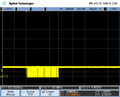
JTAG @ 50 MHz
256 bytes, ~552us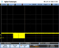
JTAG @ 50 MHz
4 bytes, ~418us


Typical halted times for memory read accesses in stop mode with J-Link PLUS @ 15 MHz:
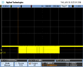
JTAG @ 15 MHz
256 bytes, ~1.02ms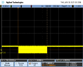
JTAG @ 15 MHz
4 bytes, ~718us


Core specific considerations
Cortex-M specifics
If the CPU implements caches:
- The RTT control block as well as all RTT buffers must start cache line aligned
- The RTT control block as well as all RTT buffers must be the multiple of a cache line in size
- In case the system provides multiple cache levels, the alignment and sizes of the control block and buffers must take the cache with the largest line size as the reference point.
- The control block and Up/Down buffer 0 are implicitly defined by SEGGER_RTT.c. So in order to make sure these fulfill the alignment requirements, SEGGER_RTT_CPU_CACHE_LINE_SIZE needs to be specified in case the cache line size is not <= 32-bytes in the used system.
- It is user application's responsibility to call a cache clean + invalidate on the RTT control block + all RTT buffers after segment init is complete but before RTT is used for the first time. A good time to do it is in main(). This makes sure that no cache line contains dirty RTT data / information which otherwise may be evicted to memory at some point during runtime. If embOS is used, it is usually safe to make sure that RTT is used after OS_InitHW() has been called, which performs a clean + invalidate of all cache lines.
- For RTT buffers that are specified and initialized at runtime (> index 0), the cache clean + invalidate needs to be performed just before calling any of the AllocBuffer() / ConfigBuffer() functions.
- In the application, the RTT control block, buffers and pointers to their names must be linked with virtual address == physical address
- The application must provide a uncached address alias to the memory where the control block + buffers are located in. The control block as well as all buffers need to be accessible via that uncached address alias.
Cortex-A specifics
- RTT background memory accesses are performed via either an AHB-AP or an AXI-AP
- The presence of an AHB-AP and AXI-AP is optional and depends on the actual MCU (if the vendor implemented them)
- For devices where no "RTT usable AP" is known by J-Link:
- The AP to be used for background memory accesses needs to be specified via a J-Link script file. For more information about J-Link script files: J-Link script files article
- It is strongly recommended to place the RTT control block and buffers in internal memory, not external one. On Cortex-A based systems, external address space is usually very sensitive and can easily cause lockups etc. in case it is accessed before it has been initialized (e.g. DDR controller init done etc.). As J-Link has no information about when external memory space init is done, there is a potential for RTT accesses from the J-Link side before the external memory is available.
- AHB/AXI-AP accesses behave like DMA accesses and bypass CPU L1 / L2 etc. caches
- If the CPU implements caches, see Cortex-M specifics.
Cortex-A MCU examples
Sample MCUs for which RTT is supported out-of-the-box:
- Xilinx Zynq 7000 series, Cortex-A9 based (RTT supported since V6.85b)
- NXP i.MX6Solo series, Cortex-A9 based, device name pattern: MCIMX6Sx (RTT supported since V6.85d)
Example project for emPower Zynq board:
- Project download
- Requirements:
- SEGGER Embedded Studio V5.10a or later
- J-Link software V6.85b or later
Cortex-R specifics
For RTT on Cortex-R, the same applies as for Cortex-A specifics.
RISC-V specifics
- RTT background memory accesses are performed either via via RISC-V system bus access (SBA) or via AHB/AXI-AP.
- The presence of SBA support is optional and depends on the actual MCU.
- AHB/AXI-AP access is only possible for setups where the RISC-V core is behind an ARM CoreSight DAP.
Support via SBA
- No specific setup is needed. J-Link detects the presence of SBA support automatically and can use RTT out-of-the-box.
Support via MEM-AP
- The presence of an AHB-AP and AXI-AP is optional and depends on the actual MCU (if the vendor implemented them)
- Support for this access method starts with J-Link software V7.50
- For devices where no "RTT usable AP" is known by J-Link:
- The AP to be used for background memory accesses needs to be specified via a J-Link script file. For more information about J-Link script files: J-Link script files article
- It is strongly recommended to place the RTT control block and buffers in internal memory, not external one. On Cortex-A based systems, external address space is usually very sensitive and can easily cause lockups etc. in case it is accessed before it has been initialized (e.g. DDR controller init done etc.). As J-Link has no information about when external memory space init is done, there is a potential for RTT accesses from the J-Link side before the external memory is available.
- AHB/AXI-AP accesses behave like DMA accesses and bypass CPU L1 / L2 etc. caches
- If the CPU implements caches:
- The RTT control block as well as all RTT buffers must start cache line aligned
- The RTT control block as well as all RTT buffers must be the multiple of a cache line in size
- In case the system provides multiple cache levels, the alignment and sizes of the control block and buffers must take the cache with the largest line size as the reference point.
- The control block and Up/Down buffer 0 are implicitly defined by SEGGER_RTT.c. So in order to make sure these fulfill the alignment requirements, SEGGER_RTT_CPU_CACHE_LINE_SIZE needs to be specified in case the cache line size is not <= 32-bytes in the used system.
- It is user application's responsibility to call a cache clean + invalidate on the RTT control block + all RTT buffers after segment init is complete but before RTT is used for the first time. A good time to do it is in main(). This makes sure that no cache line contains dirty RTT data / information which otherwise may be evicted to memory at some point during runtime. If embOS is used, it is usually safe to make sure that RTT is used after OS_InitHW() has been called, which performs a clean + invalidate of all cache lines.
- For RTT buffers that are specified and initialized at runtime (> index 0), the cache clean + invalidate needs to be performed just before calling any of the AllocBuffer() / ConfigBuffer() functions.
- In the application, the RTT control block, buffers and pointers to their names must be linked with virtual address == physical address
- The application must provide a uncached address alias to the memory where the control block + buffers are located in. The control block as well as all buffers need to be accessible via that uncached address alias.
Implementation
The SEGGER RTT implementation code is written in ANSI C and can be integrated into any embedded application by simply adding the available sources.
RTT can be used via a simple and easy to use API.
It is even possible to override the standard printf() functions to be used with RTT.
Using RTT reduces the time taken for output to a minimum and allows printing debug information to the host computer while the application is performing time critical real time tasks.
The implementation code also includes a simple version of printf() which can be used to write formatted strings via RTT. It is smaller than most standard library printf() implementations and does not require heap and only a configurable amount of stack.
The SEGGER RTT implementation is fully configurable at compile time with pre-processor defines. The number of channels and the size of the default channels can be set. Reading and writing can be made task-safe with definable Lock() and Unlock() routines.
The sources are available at two locations:
- As part of the J-Link Software and Documentation Pack, under %InstDir%/Samples/RTT
- At the SEGGER GitHub
RTT initialization
The RTT implementation expects the RAM location of the control block in either of two states:
- 0 initialized, when RTT has not been setup yet. This is the default case for most users.
- With an already setup control block. This is to allow a shared control block for multi application setups, such as bootloader + main application.
API functions
The following API functions are available in the RTT Implementation. To use them SEGGER_RTT.h has to be included in the calling sources.
SEGGER_RTT_ConfigDownBuffer()
Configure or add a down buffer by specifying its name, size and flags.
Syntax
int SEGGER_RTT_ConfigDownBuffer (unsigned BufferIndex, const char* sName, char* pBuffer, int BufferSize, int Flags);
| Parameter | Meaning |
|---|---|
| BufferIndex | Index of the buffer to configure. Must be lower than SEGGER_RTT_MAX_NUM_DOWN_CHANNELS. |
| sName | Pointer to a 0-terminated string to be displayed as the name of the channel. |
| pBuffer | Pointer to a buffer used by the channel. |
| BufferSize | Size of the buffer in Bytes. |
| Flags | Flags of the channel (blocking or non-blocking). Flags[31:24]: Used for validity check, must be zero. Flags[23:2]: Reserved for future use. Flags[1:0]: RTT operating mode. |
Return value
| Value | Meaning |
|---|---|
| >= 0 | O.K. |
| < 0 | Error |
Example
//
// Configure down buffer 1
//
SEGGER_RTT_ConfigDownBuffer(1, "DataIn", &abDataIn[0], sizeof(abDataIn),
                             SEGGER_RTT_MODE_NO_BLOCK_SKIP);
Additional information
Once a buffer is configured only the flags of the buffer should be changed.
SEGGER_RTT_ConfigUpBuffer()
Configure or add an up buffer by specifying its name, size and flags.
Syntax
int SEGGER_RTT_ConfigUpBuffer (unsigned BufferIndex, const char* sName, char* pBuffer, int BufferSize, int Flags);
| Parameter | Meaning |
|---|---|
| BufferIndex | Index of the buffer to configure. Must be lower than SEGGER_RTT_MAX_NUM_UP_CHANNELS. |
| sName | Pointer to a 0-terminated string to be displayed as the name of the channel. |
| pBuffer | Pointer to a buffer used by the channel. |
| BufferSize | Size of the buffer in Bytes. |
| Flags | Flags of the channel (blocking or non-blocking). Flags[31:24]: Used for validity check, must be zero. Flags[23:2]: Reserved for future use. Flags[1:0]: RTT operating mode. |
Return value
| Value | Meaning |
|---|---|
| >= 0 | O.K. |
| < 0 | Error |
Example
//
// Configure up buffer 1 to work in blocking mode
//
SEGGER_RTT_ConfigUpBuffer(1, "DataOut", &abDataOut[0], sizeof(abDataOut),
                           SEGGER_RTT_MODE_BLOCK_IF_FIFO_FULL);
Additional information
Once a buffer is configured only the flags of the buffer should be changed.
SEGGER_RTT_GetKey()
Reads one character from SEGGER RTT buffer 0. Host has previously stored data there.
Syntax
int SEGGER_RTT_GetKey (void);
Return value
| Value | Meaning |
|---|---|
| >= 0 | Character which has been read (0 - 255). |
| < 0 | No character available (empty buffer). |
Example
int c;
c = SEGGER_RTT_GetKey();
if (c == 'q') {
  exit();
}
SEGGER_RTT_HasKey()
Checks if at least one character for reading is available in SEGGER RTT buffer.
Syntax
int SEGGER_RTT_HasKey (void);
Return value
| Value | Meaning |
|---|---|
| 1 | At least one character is available in the buffer. |
| 0 | No characters are available to be read. |
Example
if (SEGGER_RTT_HasKey()) {
  int c = SEGGER_RTT_GetKey();
}
SEGGER_RTT_Init()
Initializes the RTT Control Block.
Syntax
void SEGGER_RTT_Init (void);
Additional information
- Should be used in RAM targets, at start of the application.
- Must be the first SEGGER_RTT_* call in case the RTT CB is linked to a non 0 initialized RAM section.
SEGGER_RTT_printf()
Send a formatted string to the host.
Syntax
int SEGGER_RTT_printf (unsigned BufferIndex, const char * sFormat, ...)
| Parameter | Meaning |
|---|---|
| BufferIndex | Index of the up channel to sent the string to. |
| sFormat | Pointer to format string, followed by arguments for conversion. |
Return value
| Value | Meaning |
|---|---|
| >= 0 | Number of bytes which have been sent. |
| < 0 | Error. |
Example
SEGGER_RTT_printf(0, "SEGGER RTT Sample. Uptime: %.10dms.", /*OS_Time*/ 890912);
// Formatted output on channel 0: SEGGER RTT Sample. Uptime: 890912ms.
Additional information
-
Conversion specifications have following syntax:
%[flags][FieldWidth][.Precision]ConversionSpecifier%Note:
Flags, FieldWidth and Precision will be ignored for all but the following specifiers: d, u, x -
Supported flags:
Flag Meaning - Left justify within the field width + Always print sign extension for signed conversions 0 Pad with 0 instead of spaces. Ignored when using '-'-flag or precision -
Supported conversion specifiers:
Conversion
specifierMeaning c Print the argument as one char d Print the argument as a signed integer u Print the argument as an unsigned integer x Print the argument as an hexadecimal integer s Print the string pointed to by the argument p Print the argument as an 8-digit hexadecimal integer. (Argument shall be a pointer to void.)
SEGGER_RTT_Read()
Read characters from any RTT down channel which have been previously stored by the host.
Syntax
unsigned SEGGER_RTT_Read (unsigned BufferIndex, char* pBuffer, unsigned BufferSize);
| Parameter | Meaning |
|---|---|
| BufferIndex | Index of the down channel to read from. |
| pBuffer | Pointer to a character buffer to store the read characters. |
| BufferSize | Number of bytes available in the buffer. |
Return value
| Value | Meaning |
|---|---|
| >= 0 | Number of bytes that have been read. |
Example
char acIn[4];
unsigned NumBytes = sizeof(acIn);
NumBytes = SEGGER_RTT_Read(0, &acIn[0], NumBytes);
if (NumBytes) {
  AnalyzeInput(acIn);
}
SEGGER_RTT_SetTerminal()
Set the "virtual" terminal to send following data on channel 0.
Syntax
void SEGGER_RTT_SetTerminal(char TerminalId);
| Parameter | Meaning |
|---|---|
| TerminalId | Id of the virtual terminal (0-9). |
Example
//
// Send a string to terminal 1 which is used as error out.
//
SEGGER_RTT_SetTerminal(1); // Select terminal 1
SEGGER_RTT_WriteString(0, "ERROR: Buffer overflow");
SEGGER_RTT_SetTerminal(0); // Reset to standard terminal
Additional information
All following data which is sent via channel 0 will be printed on the set terminal until the next change.
SEGGER_RTT_TerminalOut()
Send one string to a specific "virtual" terminal.
Syntax
int SEGGER_RTT_TerminalOut (char TerminalID, const char* s);
| Parameter | Meaning |
|---|---|
| TerminalId | Id of the virtual terminal (0-9). |
| s | Pointer to 0-terminated string to be sent. |
Return value
| Value | Meaning |
|---|---|
| >= 0 | Number of bytes sent to the terminal. |
| < 0 | Error. |
Example
//
// Sent a string to terminal 1 without changing the standard terminal.
//
SEGGER_RTT_TerminalOut(1, "ERROR: Buffer overflow.");
Additional information
SEGGER_RTT_TerminalOut does not affect following data which is sent via channel 0.
SEGGER_RTT_Write()
Send data to the host on an RTT channel.
Syntax
unsigned SEGGER_RTT_Write (unsigned BufferIndex, const char* pBuffer, unsigned NumBytes);
| Parameter | Meaning |
|---|---|
| BufferIndex | Index of the up channel to send data to. |
| pBuffer | Pointer to data to be sent. |
| NumBytes | Number of bytes to send. |
Return value
| Value | Meaning |
|---|---|
| >= 0 | Number of bytes which have been sent. |
| < 0 | Error. |
Additional information
With SEGGER_RTT_Write() all kinds of data, not only printable ones can be sent.
SEGGER_RTT_WaitKey()
Waits until at least one character is available in SEGGER RTT buffer 0. Once a character is available, it is read and returned.
Syntax
int SEGGER_RTT_WaitKey (void);
Return value
| Value | Meaning |
|---|---|
| >= 0 | Character which has been read (0 - 255). |
Example
int c = 0;
do {
  c = SEGGER_RTT_WaitKey();
} while (c != 'c');
SEGGER_RTT_WriteString()
Write a 0-terminated string to an up channel via RTT.
Syntax
unsigned SEGGER_RTT_WriteSting (unsigned BufferIndex, const char* s);
| ! Parameter | Meaning |
|---|---|
| BufferIndex | Index of the up channel to send string to. |
| s | Pointer to 0-terminated string to be sent. |
Return value
| Value | Meaning |
|---|---|
| >= 0 | Number of bytes which have been sent. |
Example
SEGGER_RTT_WriteString(0, "Hello World from your target.\n");
SEGGER_RTT_GetAvailWriteSpace()
Returns the number of bytes available in the ring buffer.
Syntax
unsigned SEGGER_RTT_GetAvailWriteSpace (unsigned BufferIndex);
| Parameter | Meaning |
|---|---|
| BufferIndex | Index of the up channel that should be checked for space. |
Return value
| Value | Meaning |
|---|---|
| >= 0 | Number of bytes that are free in the selected up buffer. |
Example
unsigned NumBytesFree;

NumBytesFree = SEGGER_RTT_GetAvailWriteSpace(0);
Configuration defines
RTT configuration
| Define / Routine | Meaning |
|---|---|
| SEGGER_RTT_MAX_NUM_DOWN_BUFFERS | Maximum number of down (to target) channels. |
| SEGGER_RTT_MAX_NUM_UP_BUFFERS | Maximum number of up (to host) channels. |
| BUFFER_SIZE_DOWN | Size of the buffer for default down channel 0. |
| BUFFER_SIZE_UP | Size of the buffer for default up channel 0. |
| SEGGER_RTT_PRINT_BUFFER_SIZE | Size of the buffer for SEGGER_RTT_printf to bulk-send chars. |
| SEGGER_RTT_LOCK() | Locking routine to prevent interrupts and task switches from within an RTT operation. |
| SEGGER_RTT_UNLOCK() | Unlocking routine to allow interrupts and task switches after an RTT operation. |
| SEGGER_RTT_IN_RAM | Indicate the whole application is in RAM to prevent falsely identifying the RTT Control Block in the init segment by defining as 1. |
Channel buffer configuration
| Define | Meaning |
|---|---|
| SEGGER_RTT_MODE_BLOCK_IF_FIFO_FULL | A call to a writing function will block, if the up buffer is full. |
| SEGGER_RTT_MODE_NO_BLOCK_SKIP | If the up buffer has not enough space to hold all of the incoming data, nothing is written to the buffer. |
| SEGGER_RTT_MODE_NO_BLOCK_TRIM | If the up buffer has not enough space to hold all of the incoming data, the available space is filled up with the incoming data while discarding any excess data. |
Note:
- SEGGER_RTT_TerminalOut() ensures that implicit terminal switching commands are always sent out, even while using the non-blocking modes.
- The buffer configuration only effects the target device buffers, not the host buffers.
Color control sequences
| Configuration | Meaning |
|---|---|
| RTT_CTRL_RESET | Reset the text color and background color. |
| RTT_CTRL_TEXT_* | Set the text color to one of the following colors.
|
| RTT_CTRL_BG_* | Set the background color to one of the following colors.
|
ARM Cortex - Background memory access
On ARM Cortex targets, background memory access necessary for RTT is performed via a so-called AHB-AP which is similar to a DMA but exclusively accessible by the debug probe.
While on Cortex-M targets there is always an AHB-AP present, on Cortex-A and Cortex-R targets this is an optional component.
Cortex-A/R targets may implement multiple APs (some even not an AHB-AP at all), so in order to use RTT on Cortex-A/R targets,
the index of the AP which is the AHB-AP that shall be used for RTT background memory access, needs to be manually specified.
This is done via the following J-Link Command string: CORESIGHT_SetIndexAHBAPToUse.
Example code
/*********************************************************************
*                    SEGGER Microcontroller GmbH                     *
*       Solutions for real time microcontroller applications         *
**********************************************************************
*                                                                    *
*            (c) 1995 - 2018 SEGGER Microcontroller GmbH             *
*                                                                    *
*      www.segger.com Support: support@segger.com                    *
*                                                                    *
**********************************************************************

----------------------------------------------------------------------
File    : RTT.c
Purpose : Simple implementation for output via RTT.
It can be used with any IDE.
---------------------------- END-OF-HEADER ---------------------------
*/

#include "SEGGER_RTT.h"

static void _Delay(int period) {
  int i = 100000*period;
  do { ; } while (i--);
}

int main(void) {
  int Cnt = 0;

  SEGGER_RTT_Init(void);
  SEGGER_RTT_WriteString(0, "Hello World from SEGGER!\n");
  do {
    SEGGER_RTT_printf(0, "%sCounter: %s%d\n",
                          RTT_CTRL_TEXT_BRIGHT_WHITE,
                          RTT_CTRL_TEXT_BRIGHT_GREEN,
                          Cnt);
    if (Cnt > 100) {
      SEGGER_RTT_TerminalOut(1, RTT_CTRL_TEXT_BRIGHT_RED"Counter overflow!");
      Cnt = 0;
    }
    _Delay(100);
    Cnt++;
  } while (1);
  return 0;
}

/*************************** End of file ****************************/
RTT Communication
Communication with the RTT implementation on the target can be done with different applications.
The functionality can even be integrated into custom applications using the J-Link SDK.
Using RTT in the target application is made easy. The implementation code is freely available for download and
can be integrated into any existing application. To communicate via RTT any J-Link can be used.
A simple way to communicate via RTT is to create a connection to localhost:19021 with a Telnet client or similar,
while a connection to J-Link (e.g. via a debug session) is active. In this case, the RTT Channel can be set via a SEGGER TELNET Config String.
The default channel is channel 0 (Terminal)
The J-Link Software and Documentation Pack comes with some more advanced applications, which demonstrates RTT functionality for different purposes:
Integrating RTT in host applications
RTT can also be integrated in any other PC application like a debugger or a data visualizer in either of two ways:
- The application can establish a socket connection to the RTT Telnet Server which is opened on localhost:19021 when a J-Link connection is active (See TELNET channel of J-Link software).
- The application creates its own connection to J-Link and uses the J-Link RTT API which is part of the J-Link SDK to directly configure and use RTT.
TELNET channel of J-Link software
The J-Link software provides a TELNET-like channel on a localhost port (default: 19021) to allow easy access to RTT data from a separate 3rd party application that may run in parallel to the debug session. The TELNET channel is very simple to use and basically all it requires is to open a local TCP/IP connection to the TELNET port and start to receive (or send) data.
For further information, please refer to: J-Link RTT TELNET Channel.
Low-power modes
Many CPU cores support low-power modes to save power while waiting for an event or interrupt. On Cortex-M for example this is achieved by executing the WFI and WFE instructions. Unfortunately, the exact behavior during low-power modes is depending on the actual device (two devices from different vendors incorporating the same Cortex-M core may behave different).
- Some devices disable the whole debug unit during low-power modes, causing J-Link to lose the connection to the device.
- Some keep the debug unit enabled but disable the internal flash and RAM, making it effectively impossible for J-Link to perform RTT requests while the target is in a low-power mode
As the target will be idle most of the time, using low-power modes will effectively make the usage of RTT impossible, as the target memory cannot be accessed 99% of the time while the application is running. Halting the target application will make the device to make up and RAM etc. becomes accessible again. This may be seen as effects like "RTT output is only seen each time the target is halted".
Solution: When using RTT, make sure that low-power modes are not used.
Samples
Troubleshooting
If you have trouble getting RTT to work with your setup, please try the following:
- Make sure the target device supports RTT. For more information, refer to Modes
- Make sure that the most recent version of the J-Link software package is used (e.g. RTT sourcecode, JLinkARM.dll, J-Link RTT Viewer, J-Link RTT Client, etc.)
- Make sure the target application uses the correct RTT mode for each buffer (Note: Every mode except for SEGGER_RTT_MODE_BLOCK_IF_FIFO_FULL may lead to loss of RTT data if the target writes RTT data faster than the host fetches it)
- Make sure the target application does not use low-power modes. For more information, refer to Low power modes
- Make sure the RTT Control Block is placed in RAM
- Make sure that there is only one application on host-side that fetches RTT data. When running multiple applications (e.g. J-Link RTT Viewer and J-Link RTT Client) in parallel, one can "steal" data from the other, leading to fragmented RTT logs
- Make sure that the RTT Control Block can be located by the J-Link DLL:
- For Auto-Detection to work, J-Link needs to be passed the correct target device name (the target core name alone is NOT sufficient for Auto-detection)
- Note: For many devices, only a part of the available RAM is specified in the J-Link DLL. If the RTT Control block is located outside of this specified area, the auto detection feature will not work and it is required to specify the address, or the search range, of the RAM area the RTT Control Block is located at.
- The address of the RTT Control block can be set using J-Link Command Strings, or when using J-Link RTT Viewer, in the Configuration Dialog.
- Address ranges for J-Link to look for the RTT Control block can be set using J-Link Command Strings, or when using J-Link RTT Viewer, in the Configuration Dialog.
- For Auto-Detection to work, J-Link needs to be passed the correct target device name (the target core name alone is NOT sufficient for Auto-detection)
- Make sure that the correct RTT channel used by the target application (e.g. J-Link RTT Viewer and J-Link RTT Client only supports data communication via channel 0).
FAQ
- Q: How does J-Link find the RTT buffer?
- A: There are two ways: If the debugger (IDE) knows the address of the SEGGER RTT Control Block, it can pass it to J-Link. This is for example done by J-Link Debugger. If another application that is not SEGGER RTT aware is used, then J-Link searches for the ID in the known target RAM during execution of the application in the background. This process normally takes just fractions of a second and does not delay program execution.
- Q: I am debugging a RAM-only application. J-Link finds an RTT buffer, but I get no output. What can I do?
- A: In case the init section of an application is stored in RAM, J-Link might falsely identify the block in the init section instead of the actual one in the data section. To prevent this, set the define SEGGER_RTT_IN_RAM to 1. Now J-Link will find the correct RTT buffer, but only after calling the first SEGGER_RTT function in the application. A call to SEGGER_RTT_Init() at the beginning of the application is recommended.
- Q: Can this also be used on targets that do not have the SWO pin?
- A: Yes, the debug interface is used. This can be JTAG or SWD (2pins only!) on most Cortex-M devices, or even the FINE interface on some Renesas devices, just like the Infineon SPD interface (single pin!).
- Q: Can this also be used on Cortex-M0 and M0+?
- A: Yes.
- Q: Some terminal output (printf) Solutions "crash" program execution when executed outside of the debug environment, because they use a Software breakpoint that triggers a hardfault without debugger or halt because SWO is not initialized. That makes it impossible to run a Debug-build in stand-alone mode. What about SEGGER-RTT?
- A: SEGGER-RTT uses non-blocking mode per default, which means it does not halt program execution if no debugger is present and J-Link is not even connected. The application program will continue to work.
- Q: I do not see any output, although the use of RTT in my application is correct. What can I do?
- A: In some cases J-Link cannot locate the RTT buffer in the known RAM region. In this case the possible region or the exact address can be set manually via a J-Link exec command:
- Set ranges to be searched for RTT buffer: SetRTTSearchRanges <RangeStart [Hex]> <RangeSize >[, <Range1Start [Hex]> <Range1Size>, ...] (e.g. "SetRTTSearchRanges 0x10000000 0x1000, 0x2000000 0x1000")
- Set address of the RTT buffer: SetRTTAddr <RTTBufferAddress [Hex]> (e.g. "SetRTTAddr 0x20000000")
- Set address of the RTT buffer via J-Link Control Panel -> RTTerminal
Note:
J-Link exec commands can be executed in most applications, for example in- J-Link Commander via "exec <Command>"
- J-Link GDB Server via "monitor exec <Command>"
- IAR EW via "__jlinkExecCommand("<Command>");" from a macro file.