Difference between revisions of "Renesas EK-RA6M5"
(→Preparing for J-Link) |
|||
| Line 8: | Line 8: | ||
=Preparing for J-Link= |
=Preparing for J-Link= |
||
| − | * Attach the board over the debug USB-port to your PC (J10 - J- |
+ | * Attach the board over the debug USB-port to your PC (J10 - J-Link OB). This will power the board as well. |
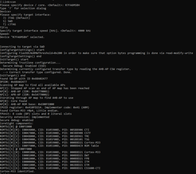
* Verify the Connection with e.g. [https://wiki.segger.com/J-Link_cannot_connect_to_the_CPU#Verify_functionality_using_J-Link_Commander J-Link Commander]. The output should look as follows: |
* Verify the Connection with e.g. [https://wiki.segger.com/J-Link_cannot_connect_to_the_CPU#Verify_functionality_using_J-Link_Commander J-Link Commander]. The output should look as follows: |
||
[[File:ek_ra6m5_commander.PNG|400px]] |
[[File:ek_ra6m5_commander.PNG|400px]] |
||
Latest revision as of 10:40, 7 April 2021
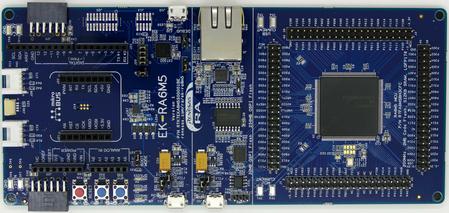
This article describes specifics for the Renesas EK-RA6M5 evaluation board. It can be used to test & verify Renesas RA6M5 support.
Minimum requirements
- J-Link software V7.00 or later
Preparing for J-Link
- Attach the board over the debug USB-port to your PC (J10 - J-Link OB). This will power the board as well.
- Verify the Connection with e.g. J-Link Commander. The output should look as follows:
Example Project
The following example project was created with the SEGGER Embedded Studio project wizard and runs out-of-the-box on the Renesas EK-RA6M5. It is a simple Hello World sample linked into the internal program flash.
SETUP
- J-Link software: V7.00
- Embedded Studio:
- Hardware: Renesas EK-RA6M5
- Link: File:TestAPP ProgFlash RA6M5.zip

